Hyundai Ioniq (AE): Seat Electrical / Seat Heater. Repair procedures
Hyundai Ioniq (AE) 2017-2022 Service & Repair Manual / Body Electrical System / Seat Electrical / Seat Heater. Repair procedures
| Inspection |
Front Seat Heater
| 1. | Check for continuity and measure the resistance between terminals No 3 and No 6.
|

| 2. | Operate the seat heater after connecting the connector, and then check the thermostat by measuring the temperature of seat surface.
|
Rear Seat Heater
| 1. | Check for continuity and measure the resistance between terminals No 1 and No 4.
|
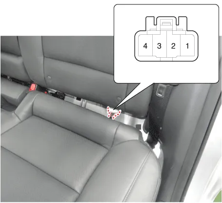
| 2. | Operate the seat heater after connecting the connector, and then check the thermostat by measuring the temperature of seat surface.
|
Seat Heater Unit Diagnosis Mode
| 1. | You can enter the diagnosis mode by turning the seat heater button on. |
| 2. | You can enter the diagnosis mode by referring to following description.
|
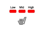
| 3. | After entering the diagnosis mode, you can check what failed by checking the blinking LED. [Driver / Passenger Seat Heater]
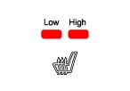
[Rear Seat Heater]
|
| 4. | You can check the malfunctioning by checking the blinking LED. |
| 5. | Pressing the IGN OFF button will end the diagnosis mode for the heater seat. |
| 6. | You can check whether the heating seat system works properly after turning the IGN ON. If you want to check the error code, you can refer to the procedure of 2 above. |
Circuit Diagram[Front Seat Heater (Non-Air Ventilation)][Rear Seat Heater (Bench Type)]
Components[Front Seat]1. Driver seater heater switch2. Passenger seater heater switch[Rear Seat]1. Seat heater switch
Other information:
Hyundai Ioniq (AE) 2017-2022 Service & Repair Manual: Smart Cruise Control (SCC) Switch. Repair procedures
Removal1.Disconnect the negative (-) battery terminal.2.Remove the steering wheel assembly.(Refer to Steering System -"Steering Wheel")3.Remove the steering back cover (A).4.Remove the steering remote control connector (A).5.Remove the steering remote control (A), after loosening the screws.
Hyundai Ioniq (AE) 2017-2022 Service & Repair Manual: Specifications
S
Categories
- Manuals Home
- Hyundai Ioniq Owners Manual
- Hyundai Ioniq Service Manual
- Transmission Gear Oil. Repair procedures
- Suspension System
- Theft-alarm System
- New on site
- Most important about car

Copyright © 2026 www.hioniqae.com - 0.0134