Hyundai Ioniq (AE): Front Radar System / Smart Cruise Control (SCC) Switch. Repair procedures
Hyundai Ioniq (AE) 2017-2022 Service & Repair Manual / Advanced Driver Assistance System (ADAS) / Front Radar System / Smart Cruise Control (SCC) Switch. Repair procedures
| Removal |
| 1. | Disconnect the negative (-) battery terminal. |
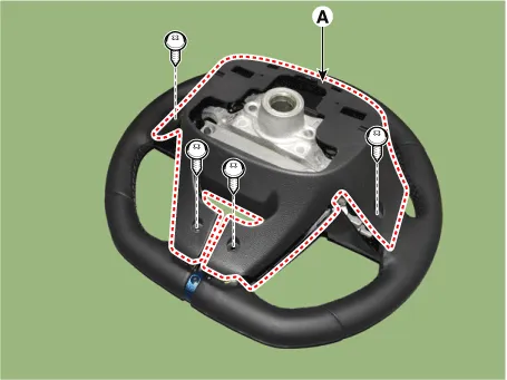
| 2. | Remove the steering wheel assembly. (Refer to Steering System -"Steering Wheel") |
| 3. | Remove the steering back cover (A).
|
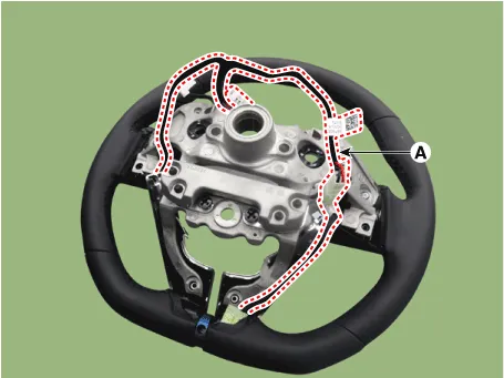
| 4. | Remove the steering remote control connector (A).
|
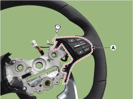
| 5. | Remove the steering remote control (A), after loosening the screws.
|
| Installation |
| 1. | Install the steering wheel remote control after connecting the connector. |
| 2. | Connect the negative (-) battery terminal. |
| Inspection |
| 1. | Remove the cruise control switch.
|
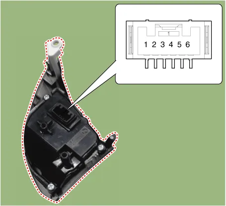
| 2. | Measure resistance between terminals on the control switch when each function switch is ON. (switch is depressed).
|
| 3. | If not within specification, replace switch. |
Circuit Diagram[Curise + SCC]
Other information:
Hyundai Ioniq (AE) 2017-2022 Service & Repair Manual: Auto Defogging Sensor. Description and operation
DescriptionThe auto defogging sensor is installed on the front window glass. The sensor judges and sends signal if moisture occurs to blow out wind for defogging. The air conditioner control module receives signal from the sensor and restrains moisture and eliminate defog by controlling the intake actuator, A/C, auto defogging actuator, blower moto
Hyundai Ioniq (AE) 2017-2022 Service & Repair Manual: Repair procedures
Replacement1.Remove the battery (-) terminal.2.Remove the engine room under cover.(Refer to Engine Mechanical System - "Engine Room Under Cover")3.Remove the heater hose (A) and AEWP hose (B).4.Disconnect the lock pin to remove the heater hose pump connector (A).
Categories
- Manuals Home
- Hyundai Ioniq Owners Manual
- Hyundai Ioniq Service Manual
- Jump Starting
- Repair procedures
- Theft-alarm System
- New on site
- Most important about car

Copyright © 2026 www.hioniqae.com - 0.0104