
Hyundai Ioniq (AE): Smart Key System / Smart Key. Repair procedures
| Smart Key |
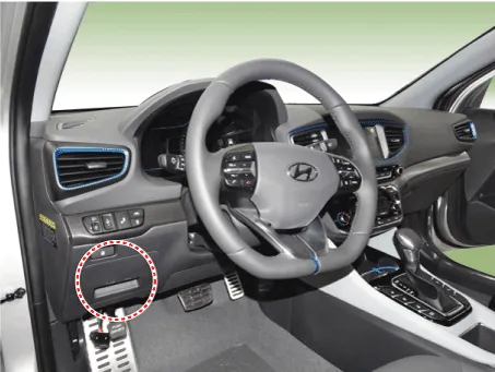
| 1. | Connect the DLC cable of GDS to the data link connector (16 pins) in driver side crash pad lower panel, turn the power on GDS.
|
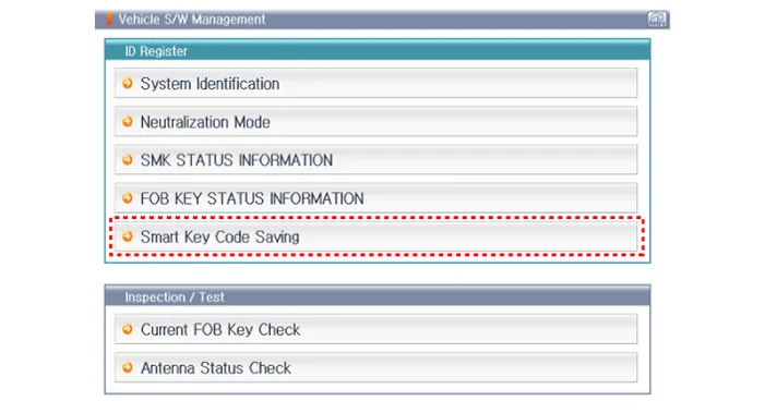
| 2. | Select the vehicle model and then do "Smart Key Code Saving".
|
| 3. | After selecting "Smart Key Teaching" menu, push "Enter" key, then the screen will be shown as below.
|
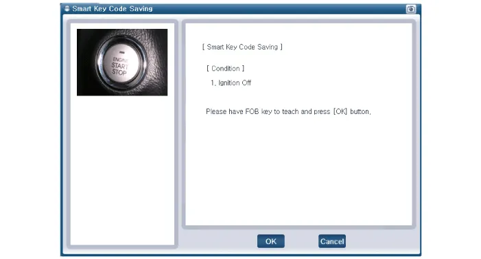
| 4. | After having the teaching smart key, push "ENTER" key. |
| 5. | Input the "Pin Code" for first key teaching.
|
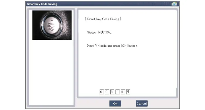
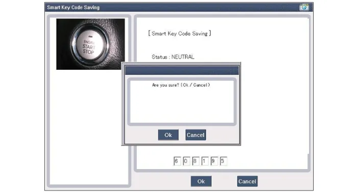
| 6. | Press the SSB with smart key within 5 sec after pressing "OK".
|
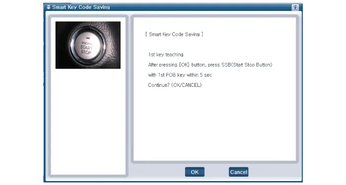
| 7. | Confirm the message "First Key Teaching Completed".
|
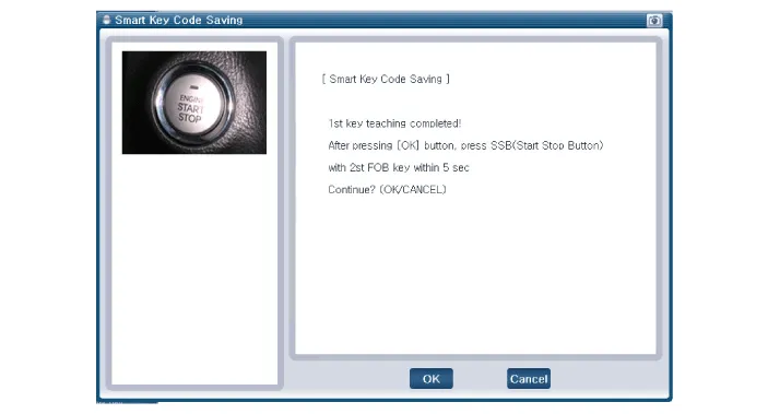
| 8. | Press the SSB with smart key within 5 sec after pressing "OK".
|
| 9. | Confirm the message "Second Key Teaching Completed".
|
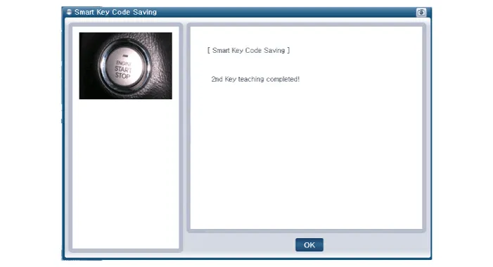
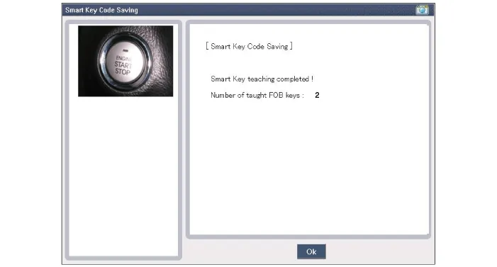
| 10. | Then the screen will be shown as below when key teaching process is completed.
|
DescriptionThe SMART KEY system is a system that allows the user to access and operate a vehicle in a very convenient way. To access the vehicle, no traditional key or remote control unit is needed.
Components (1) No Connector A Connector B Connector C 1Battery (+)_LOADIGN2 Relay outputImmobilizer antenna power input2Battery (+)_CPUIGN1 Relay outputWheel speed signal input3Antenna ground (Internal1)-SSB Switch1 signal input4---5Antenna ground (Internal2)B-CAN (Low)ESCL Unlock switch signal input6Antenna ground (Assist)EMS CANP Position switch signal input7Antenna ground (Trunk)B-CAN (High)Brake switch signal input8Antenna ground (Driver)B-CAN (Low)Ignition 2 signal input9-P-CAN (Low)Ignition 1 signal input10SSB Illumination power (Output)P-CAN (High)Starter relay output11External buzzer output-Immoblizer antenna ground12ESCL Power outputACC Relay outputRPM Signal input13--SSB Switch2 signal input14Antenna power (Internal1)Signal groundDriver toggle button switch signal input15--Assiste toggle button switch signal input16Antenna power (Internal2)SSB ACC LED OutputStarter relay feedback signal input17Antenna power (Assist)SSB IGN LED Output Stop lamp fuse signal input18Antenna power (Trunk)-ACC Signal input19Antenna power (Driver)--20-SSB Illumination groundPower ground21ESCL Enable output-22ESCL Ground outputWireless charging module output
Other information:
Hyundai Ioniq (AE) 2017-2022 Service & Repair Manual: emperature Control Actuator. Repair procedures
Inspection1.Turn the ignition switch OFF.2.Disconnect the temperature control actuator connector.3.Verify that the temperature control actuator operates to the cool position when connecting 12V to terminal 3 and grounding terminal 7.Verify that the temperature control actuator operates to the warm position when connected in reverse.
Hyundai Ioniq (AE) 2017-2022 Service & Repair Manual: Intake Actuator. Components and components location
C
Categories
- Manuals Home
- Hyundai Ioniq Owners Manual
- Hyundai Ioniq Service Manual
- Jump starting procedure
- Body (Interior and Exterior)
- Hybrid Control System
- New on site
- Most important about car
