Hyundai Ioniq (AE): Brake System / Front Disc Brake. Repair procedures
| Removal |
| 1. | Loosen the wheel nuts slightly. Raise the vehicle, and make sure it is securely supported. |
| 2. | Remove the front wheel and tire (A) from the front hub.
|

| 3. | Loosen the brake hose mounting bolt and then remove the brake hose bracket.
|

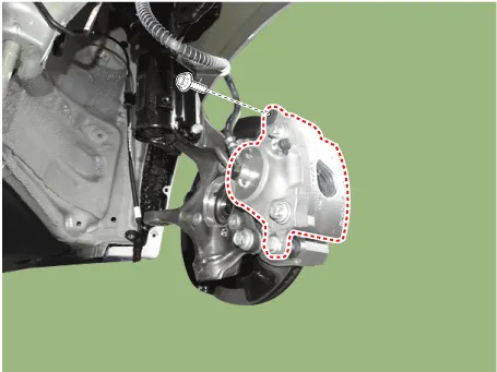
| 4. | Put down the caliper body after loosening the guide rod bolt.
|
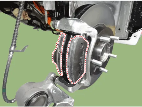
| 5. | Remove the pad return spring (A).
|


| 6. | Remove the brake pad.
|
| 7. | Separate the pad retainer. And remove the caliper carrier by loosening the caliper mounting bolts.
|
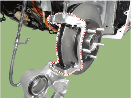
| 8. | Remove the front brake disc by loosening the screws.
|

| Replacement |
| 1. | Loosen the wheel nuts slightly. Raise the vehicle, and make sure it is securely supported. |
| 2. | Remove the front wheel and tire (A) from the front hub.
|
| 3. | Loosen the brake hose mounting bolt and then remove the brake hose bracket.
|
| 4. | Put down the caliper body after loosening the guide rod bolt.
|
| 5. | Remove the pad return spring (A).
|
| 6. | Remove the brake pad.
|
| 7. | Install the pad return spring (A).
|
| 8. | Use a SST (09581-2T100) when installing the brake caliper assembly.
|

| 9. | Install the caliper body (A) then tighten the guide rod bolt (B).
|

| Inspection |
| 1. | Check the brake pads for wear and fade. |
| 2. | Check the brake disc for damage and cracks. |
| 3. | Remove all rust and contamination from the surface, and measure the disc thickness at 24 points, at least, of same distance (5mm) from the brake disc outer circle.
|

| 4. | If wear exceeds the limit, replace the discs and pad assembly left and right of the vehicle. |
| 1. | Check the pad wear. Measure the pad thickness and replace it, if it is less than the specified value.
|
| 2. | Check that grease is applied, to sliding contact points. Check for metal damage to the pad and backing.
|

| 1. | Place a dial gauge about 10mm (0.2 in.) from the outer circumference of the brake disc, and measure the runout of the disc.
|

| 2. | If the runout of the brake disc exceeds the limit specification, replace the disc, and then measure the runout again. |
| 3. | If the runout does not meet the limit specification, remove the disc, turn it 180° and reinstall. Then check the runout of the brake disc again. |
| 4. | If the runout cannot be corrected by changing the position of the brake disc, replace the brake disc. |
| Installation |
| 1. | To install, reverse the removal procedure. |
| 2. | Use a SST (09581-2T100) when installing the brake caliper assembly.
|
| 3. | After installing, bleed the brake system. (Refer to Brake System - "ESP System Bleeding") |
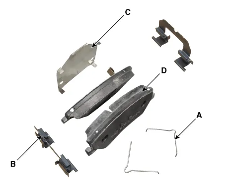
Components1. Bleed screw2. Caliper body3. Pad inner shim4. Brake pad5. Pad return spring6. Caliper carrier7. Pad retainer
Components[EPB None Apply]1. Brake pad2. Pad return spring3. Caliper carrier4. Pad retainer5. Caliper body6. Bleed screw7. Stopper8. Return spring9. Operating lever[EPB Apply]1.
Other information:
Hyundai Ioniq (AE) 2017-2022 Service & Repair Manual: Ambient Temperature Sensor. Repair procedures
Inspection1.Check the resistance of the ambient temperature sensor between terminals 1 and 2 whether it changes by changing the ambient temperature.1. Ambient Sensor (+)2. Sensor groundSpecification Ambient temperature [°C (°F)] Resistance between terminal 1 and 2 (
Hyundai Ioniq (AE) 2017-2022 Service & Repair Manual: Heater Unit. Components and components location
Component Location1. Heater unit assemblyCompoents1. Heater core cover2. Heater core & Seal assembly3. Mode actuator [LH]4. Temperature control actuator [LH]5. Shower duct [LH]6. Duct sensor [Floor]7. PTC Heater8. Duct sensor [Vent]9. Heater & Evaporator lower case10.
Categories
- Manuals Home
- Hyundai Ioniq Owners Manual
- Hyundai Ioniq Service Manual
- Body (Interior and Exterior)
- General Information
- Heating, Ventilation and Air Conditioning
- New on site
- Most important about car
