Hyundai Ioniq (AE): Brake System / Rear Disc Brake. Components and components location
| Components |
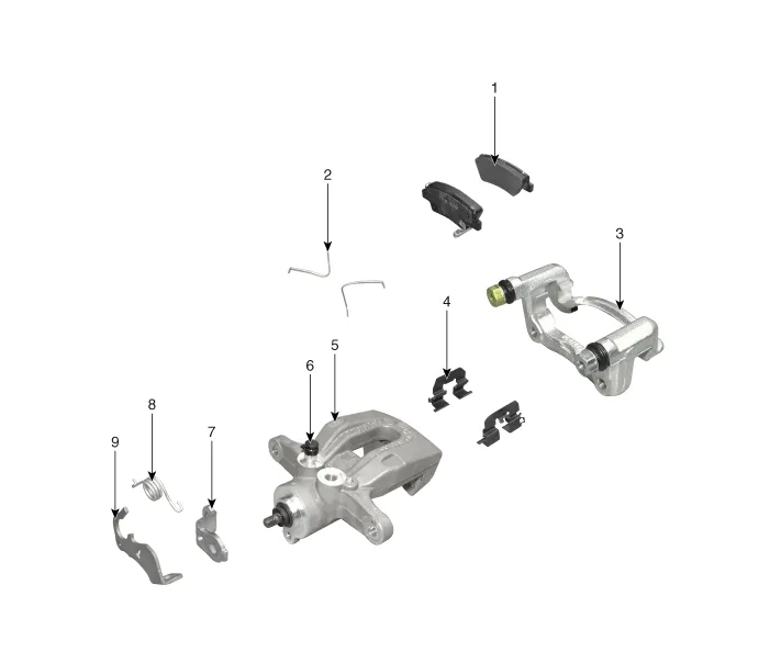
| 1. Brake pad 2. Pad return spring 3. Caliper carrier 4. Pad retainer 5. Caliper body | 6. Bleed screw 7. Stopper 8. Return spring 9. Operating lever |
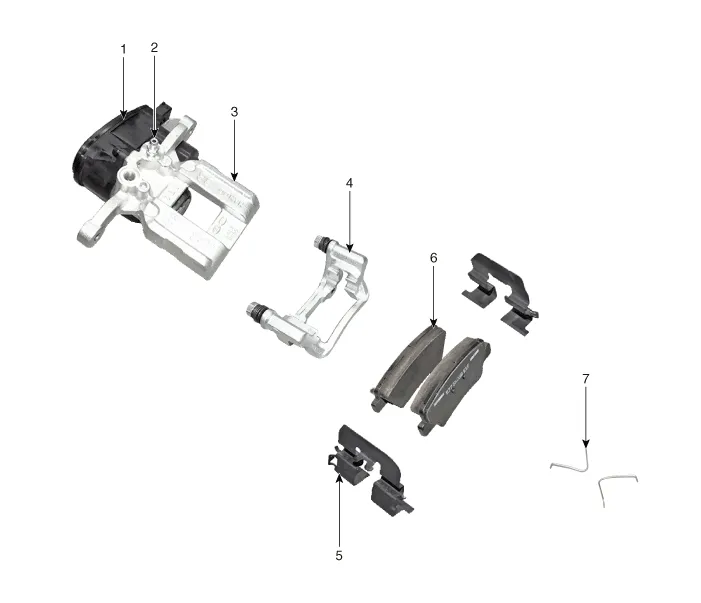
| 1. EPB Actuator 2. Bleed screw 3. Caliper body 4. Caliper carrier | 5. Pad retainer 6. Brake pad 7. Pad return spring |
Removal1.Loosen the wheel nuts slightly.Raise the vehicle, and make sure it is securely supported.2.Remove the front wheel and tire (A) from the front hub.
Removal[EPB None Apply]1.Loosen the wheel nuts slightly.Raise the vehicle, and make sure it is securely supported.2.Remove the rear wheel and tire (A) from the rear hub.
Other information:
Hyundai Ioniq (AE) 2017-2022 Service & Repair Manual: Ambient Temperature Sensor. Description and operation
DescriptionThe ambient temperature sensor is located at the front of the condenser and detects ambient air temperature. It is a negative type thermistor; resistance will increase with lower temperature, and decrease with higher temperature.The sensor output will be used for discharge temperature control, temperature regulation door contrl, blower m
Hyundai Ioniq (AE) 2017-2022 Service & Repair Manual: Blower Unit. Components and components location
Component Location1. Blower unit assembly Components1. Duct Seal2. Intake duct case3. Air intake door assembly4. Intake door5. Seal6. Intake duct case (A)7. Air filter cover (A)8. Intake actuator9. Air filter cover10. Air filter 11. Blower unit pad12.
Categories
- Manuals Home
- Hyundai Ioniq Owners Manual
- Hyundai Ioniq Service Manual
- Body (Interior and Exterior)
- General Information
- DCT(Dual Clutch Transmission) System
- New on site
- Most important about car
