Hyundai Ioniq (AE): Brake System / Rear Disc Brake. Repair procedures
Hyundai Ioniq (AE) 2017-2022 Service & Repair Manual / Brake System / Brake System / Rear Disc Brake. Repair procedures
| Removal |
[EPB None Apply]
| 1. | Loosen the wheel nuts slightly. Raise the vehicle, and make sure it is securely supported. |
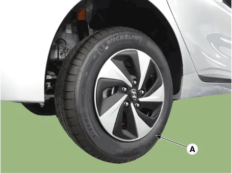
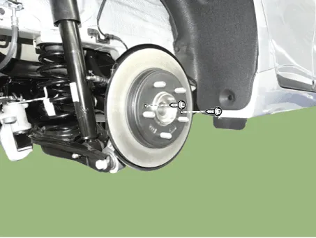
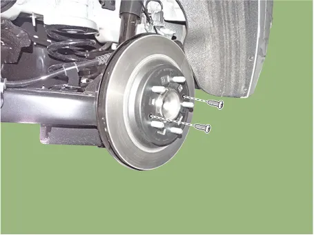
| 2. | Remove the rear wheel and tire (A) from the rear hub.
|

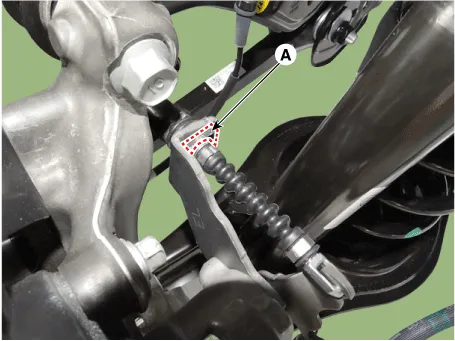
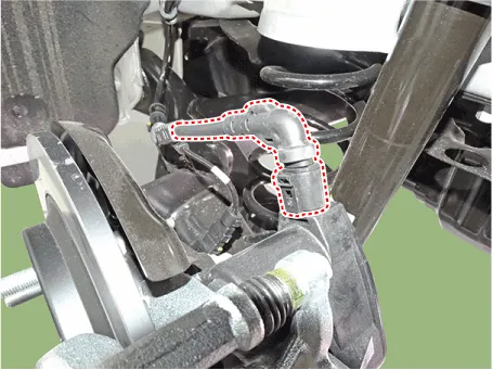
| 3. | Remove the parking brake cable fixed clip (A).
|
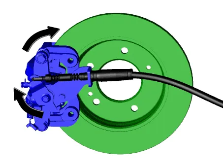
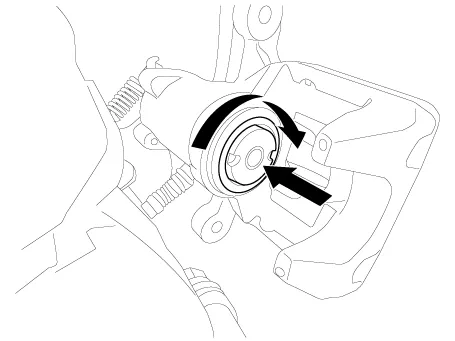
| 4. | Pull the operating lever as a direction of arrow in the illustration below and then remove the parking brake cable.
|
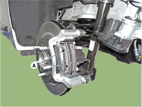
| 5. | Loosen the guide rod bolt and then pivot the caliper body up out of the way.
|
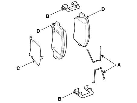
| 6. | Remove the pad return spring (A).
|
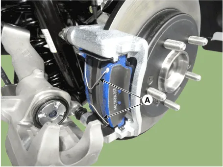
| 7. | Separate the brake pad and pad retainer.
|

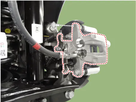
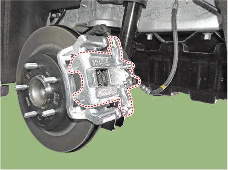
| 8. | Loosen the caliper mounting bolts and then removethe rear caliper assembly (A).
|

| 9. | Remove the rear brake disc by loosening the screws.
|
[EPB Apply]
| 1. | Loosen the wheel nuts slightly. Raise the vehicle, and make sure it is securely supported. |
| 2. | Remove the rear wheel and tire (A) from the rear hub.
|
| 3. | Disconnect the EPB connector.
|
| 4. | Loosen the guide rod bolt and then remove the caliper body.
|
| 5. | Remove the pad return spring (A).
|
| 6. | Remove the brake pad.
|
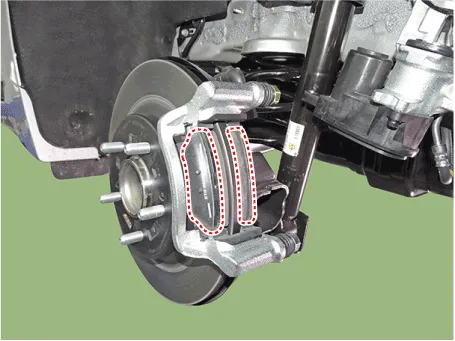
| 7. | Remove the pad retainer (A).
|
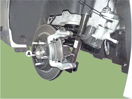
| 8. | Loosen the caliper mounting bolts and then removethe rear caliper assembly (A).
|
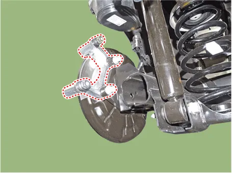
| 9. | Remove the rear brake disc by loosening the screws.
|
| Replacement |
Brake Pad
| [EPB None Apply] |
| 1. | Loosen the wheel nuts slightly. Raise the vehicle, and make sure it is securely supported. |
| 2. | Remove the rear wheel and tire (A) from the rear hub.
|
| 3. | Remove the parking brake cable fixed clip (A).
|
| 4. | Pull the operating lever as a direction of arrow in the illustration below and then remove the parking brake cable.
|
| 5. | Loosen the guide rod bolt and then pivot the caliper body up out of the way.
|
| 6. | Remove the pad return spring (A).
|
| 7. | Replace the brake pad and pad retainer.
|
| 8. | Install the pad return spring (A).
|
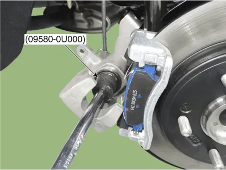
| 9. | Use a SST (09580-0U000) when installing the brake caliper assembly.
|
| 10. | Install the caliper body (A) then tighten the guide rod bolt (B).
|
| 11. | Pull the operating lever as a direction of arrow in the illustration below and then install the parking brake cable.
|
| 12. | Install the parking brake cable fixed clip (A).
|
| 13. | Install the rear wheel and tire (A) from the rear hub.
|
| [EPB Apply] |
| 1. | Loosen the wheel nuts slightly. Raise the vehicle, and make sure it is securely supported. |
| 2. | Remove the rear wheel and tire (A) from the rear hub.
|
| 3. | Disconnect the EPB connector.
|
| 4. | Loosen the guide rod bolt and then remove the caliper body.
|
| 5. | Remove the pad return spring (A).
|
| 6. | Remove the brake pad.
|
| 7. | Remove the pad retainer (A).
|
| 8. | Install the pad return spring (A).
|
| 9. | Install the caliper body (A) then tighten the guide rod bolt (B).
|
| 10. | Connect the EPB connector.
|
| 11. | Install the rear wheel and tire (A) from the rear hub.
|
| Inspection |
Rear Brake Disc Thickness Check
| 1. | Check the brake pads for wear and fade. |
| 2. | Check the brake disc for damage and cracks. |
| 3. | Remove all rust and contamination from the surface, and measure the disc thickness at 24 points, at least, of same distance (5mm) from the brake disc outer circle.
|

| 4. | If wear exceeds the limit, replace the discs and pad assembly left and right of the vehicle. |
Rear Brake Pad Check
| 1. | Check the pad wear. Measure the pad thickness and replace it, if it is less than the specified value.
|
| 2. | Check the damage of pad, backing metal and contamination with grease. |
Rear Brake Disc Runout Check
| 1. | Place a dial gauge about 10mm (0.2 in.) from the outer circumference of the brake disc, and measure the runout of the disc.
|

| 2. | If the runout of the brake disc exceeds the limit specification, replace the disc, and then measure the runout again. |
| 3. | If the runout exceeds the limit specification, install the brake disc after turning it 180° and then check the runout of the brake disc again. |
| 4. | If the runout cannot be corrected by changing the position of the brake disc, replace the brake disc. |
| Installation |
| 1. | To install, reverse the removal procedure. |
| 2. | Use a SST (09580-0U000) when installing the brake caliper assembly.
|
| 3. | After installing, bleed the brake system. (Refer to Brake System - "Brake System Bleeding") |
| Adjustment |
Parking Brake
|
| 1. | Remove the floor console to reach the adjusting nut. |
| 2. | Loosen the parking brake cable until both operating levers rest in fully off position. |
| 3. | Bring the brake pads in their operating position by pressing the brake pedal down several times until there is resistance. |
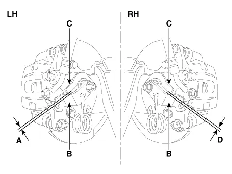
| 4. | Tension the parking brake cable by tightening the adjusting nut, until the operating levers on both calipers lift from the stop, up to a distance of (A) and (D) between operating lever (B) and stopper (C).
|
| 5. | Refit the floor console. |
| 6. | Parking brake lever in the car must be in fully loosened position. |
| 7. | If the handbrake cables where changed, actuate the parking brake a few times with maximum force to stretch the parking brake cables, and then control adjusting as above. |
| 8. | Check the wheels of their free operation. |
| 9. | Test drive. |
Components[EPB None Apply]1. Brake pad2. Pad return spring3. Caliper carrier4. Pad retainer5. Caliper body6. Bleed screw7. Stopper8. Return spring9. Operating lever[EPB Apply]1.
Components Location1. Brake pedal member assembly2. Stop lamp switch3. Brake pedal arm assembly4. Brake pedal pad5. Pedal stroke sensor
Other information:
Hyundai Ioniq (AE) 2017-2022 Service & Repair Manual: Photo Sensor. Repair procedures
Inspection1.Turn the ignition switch ON.2.Connect the GDS.3.Emit intensive light toward the photo sensor using a lamp, and check the output voltage change.4.The voltage will rise with higher intensive light and reduce with lower intensive light.1. Auto light signal2.
Hyundai Ioniq (AE) 2017-2022 Service & Repair Manual: Components and components location
C
Categories
- Manuals Home
- Hyundai Ioniq Owners Manual
- Hyundai Ioniq Service Manual
- How to Connect Portable Charger (ICCB: In-Cable Control Box)
- Jump Starting
- Theft-alarm System
- New on site
- Most important about car

Copyright © 2026 www.hioniqae.com - 0.0235