Hyundai Ioniq (AE): Brake System / Stop Lamp Switch. Components and components location
| Components Location |
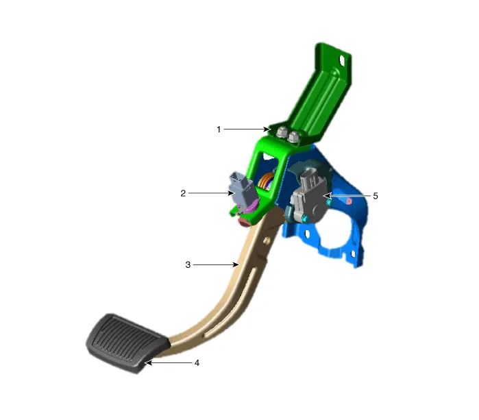
| 1. Brake pedal member assembly 2. Stop lamp switch 3. Brake pedal arm assembly | 4. Brake pedal pad 5. Pedal stroke sensor |
Removal[EPB None Apply]1.Loosen the wheel nuts slightly.Raise the vehicle, and make sure it is securely supported.2.Remove the rear wheel and tire (A) from the rear hub.
Schematic DiagramSystem Circuit DiagramTerminal Function Teminal Description 1IGN12Engine Control Module (ECM)3B+4Stop Lamp
Other information:
Hyundai Ioniq (AE) 2017-2022 Service & Repair Manual: Auto Defogging Sensor. Repair procedures
Diagnosis With GDS1.The heating, ventilation and air conditioning can be quickly diagnosed failed parts with vehicle diagnostic system (GDS).※ The diagnostic system (GDS) provides the following information.(1) Self diagnosis : Checking the failure code (DTC) and display.
Hyundai Ioniq (AE) 2017-2022 Service & Repair Manual: Blower Unit. Components and components location
Component Location1. Blower unit assembly Components1. Duct Seal2. Intake duct case3. Air intake door assembly4. Intake door5. Seal6. Intake duct case (A)7. Air filter cover (A)8. Intake actuator9. Air filter cover10. Air filter 11. Blower unit pad12.
Categories
- Manuals Home
- Hyundai Ioniq Owners Manual
- Hyundai Ioniq Service Manual
- Hybrid Vehicle Engine Compartment
- Suspension System
- Transmission Gear Oil. Repair procedures
- New on site
- Most important about car
