Hyundai Ioniq (AE): Motor Driven Power Steering / Steering Gear Box. Repair procedures
| Removal |
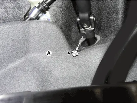
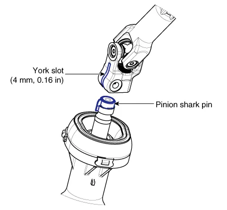
| 1. | Loosen the bolt (A) and then disconnect the universal joint assembly from the pinion of the steering gear box.
|

| 2. | Loosen the wheel nuts slightly. Raise the vehicle, and make sure it is securely supported. |
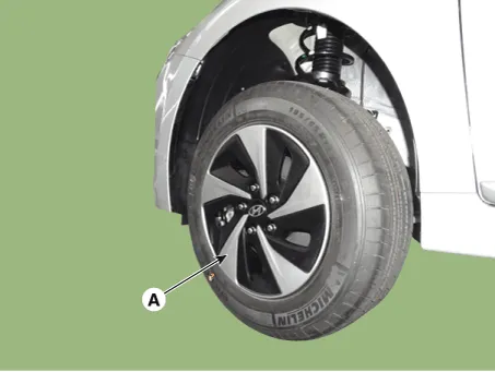
| 3. | Remove the front wheel and tire (A) from the front hub.
|
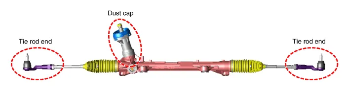
| 4. | Remove the tie rod end ball joint.
|
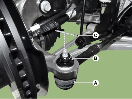
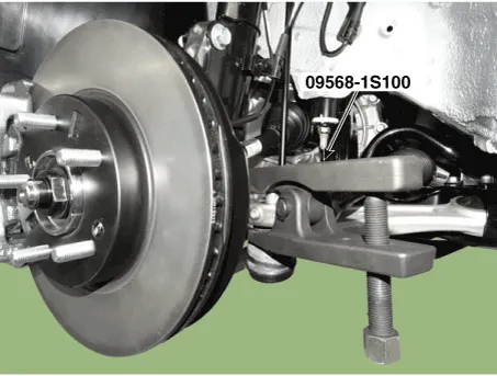
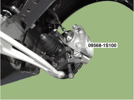
| 5. | Loosen the lower arm nut and then remove the lower arm ball joint by using SST(09568-1S100).
|
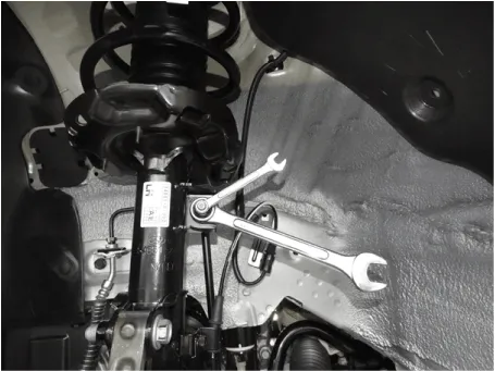
| 6. | Disconnect the stabilizer link with the front strut assembly after loosening the nut.
|
| 7. | Remove the front subframe. (Refer to Suspension System - "Sub Frame") |
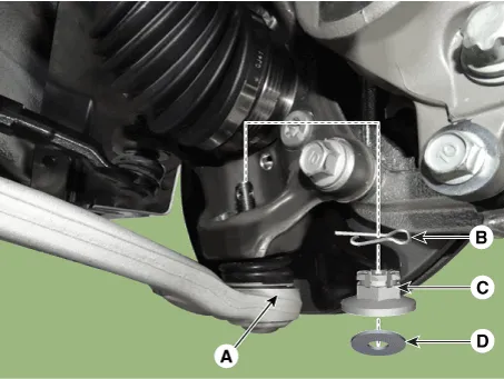
| 8. | Remove the protector (A).
|
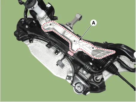
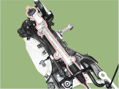
| 9. | Remove the steering gearbox from the front sub frame by loosening the mounting bolts.
|
| 10. | To install, reverse the removal procedure. |
| 11. | Check the front alignment. (Refer to Suspension System - "Front Alignment") |
| Replacement |
|
Removal1.Disconnect the battery negative cable from the battery and then wait for at least 30 seconds.2.Turn the steering wheel so that the front wheels are placed in the straight ahead position.
Other information:
Hyundai Ioniq (AE) 2017-2022 Service & Repair Manual: PTC Heater. Description and operation
DescriptionThe PTC (Positive Temperature Coefficient) heater is installed at the exit or the backside of the heater core.The PTC heater is an electric heater using a PTC element as an auxiliary heating device that supplements deficiency of interior heat source in highly effective hybrid engine.
Hyundai Ioniq (AE) 2017-2022 Service & Repair Manual: Repair procedures
Replacement1.Remove the battery (-) terminal.2.Remove the engine room under cover.(Refer to Engine Mechanical System - "Engine Room Under Cover")3.Remove the heater hose (A) and AEWP hose (B).4.Disconnect the lock pin to remove the heater hose pump connector (A).
Categories
- Manuals Home
- Hyundai Ioniq Owners Manual
- Hyundai Ioniq Service Manual
- Theft-alarm System
- Heating, Ventilation and Air Conditioning
- Jump starting procedure
- New on site
- Most important about car
