
Hyundai Ioniq (AE): Immobilizer System / Antenna Coil. Repair procedures
| Removal |
| 1. | Disconnect the negative (-) battery terminal. |
| 2. | Remove the steering column shroud panel. (Refer to Body - "Steering Column Shroud Panel") |
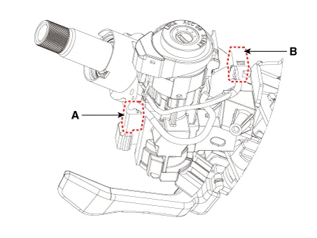
| 3. | Disconnect the 6P connector (B) of the coil antenna and then remove the coil antenna (A) after loosening the screw.
|
| Installation |
| 1. | Install the coil antenna and connect the 6P connector. |
| 2. | Install the steering column shroud panel. |
| 3. | Connect the negative (-) battery terminal. |
Removal1.Disconnect the negative (-) battery terminal.2.Remove the main crash pad assembly.(Refer to Body - "Main Crash Pad Assembly")3.Discnnect the connector of the immobilizer unit and then remove the immobilizer unit (A) after loosening a nut.
Other information:
Hyundai Ioniq (AE) 2017-2022 Service & Repair Manual: Photo Sensor. Repair procedures
Inspection1.Turn the ignition switch ON.2.Connect the GDS.3.Emit intensive light toward the photo sensor using a lamp, and check the output voltage change.4.The voltage will rise with higher intensive light and reduce with lower intensive light.1. Auto light signal2.
Hyundai Ioniq (AE) 2017-2022 Service & Repair Manual: emperature Control Actuator. Repair procedures
Inspection1.Turn the ignition switch OFF.2.Disconnect the temperature control actuator connector.3.Verify that the temperature control actuator operates to the cool position when connecting 12V to terminal 3 and grounding terminal 7.Verify that the temperature control actuator operates to the warm position when connected in reverse.
Categories
- Manuals Home
- Hyundai Ioniq Owners Manual
- Hyundai Ioniq Service Manual
- Troubleshooting
- If the 12 Volt Battery is Discharged (Hybrid Vehicle)
- General Information
- New on site
- Most important about car
