Hyundai Ioniq (AE): Engine Control System / Description and operation
If the Gasoline Engine Control system components (sensors, ECM, injector, etc.) fail, interruption to the fuel supply or failure to supply the proper amount of fuel for various engine operating conditions will result. The following situations may be encountered.
| 1. | Engine is hard to start or does not start at all. |
If any of the above conditions are noted, first perform a routine diagnosis that includes basic engine checks (ignition system malfunction, incorrect engine adjustment, etc.). Then, inspect the Gasoline Engine Control system components with the GDS.
| •
| Before removing or installing any part, read the diagnostic trouble codes and then disconnect the battery negative (-) terminal. |
| •
| Before disconnecting the cable from battery terminal, turn the ignition switch to OFF. Removal or connection of the battery cable during engine operation or while the ignition switch is ON could cause damage to the ECM. |
| •
| The control harnesses between the ECM and heated oxygen sensor are shielded with the shielded ground wires to the body in order to prevent the influence of ignition noises and radio interference. When the shielded wire is faulty, the control harness must be replaced. |
| •
| When checking the generator for the charging state, do not disconnect the battery '+' terminal to prevent the ECM from damage due to the voltage. |
| •
| When charging the battery with the external charger, disconnect the vehicle side battery terminals to prevent damage to the ECM. |
|
Malfunction Indicator Lamp (MIL)
A malfunction indicator lamp illuminates to notify the driver that there is a problem with the vehicle. However, the MIL will go off automatically after 3 subsequent sequential driving cycles without the same malfunction. Immediately after the ignition switch is turned on (ON position - do not start), the MIL will illuminate continuously to indicate that the MIL operates normally.
Faults with the following items will illuminate the MIL.
| •
| Manifold Absolute Pressure Sensor (MAPS) |
| •
| Intake Air Temperature Sensor (IATS) |
| •
| Engine Coolant Temperature Sensor (ECTS) |
| •
| Throttle Position Sensor (TPS) [integrated into ETC Module] |
| •
| Upstream Oxygen Sensor |
| •
| Upstream Oxygen Sensor Heater |
| •
| Downstream Oxygen Sensor |
| •
| Downstream Oxygen Sensor Heater |
| •
| Crankshaft Position Sensor (CKPS) |
| •
| Camshaft Position Sensor (CMPS) |
| •
| Evaporative Emission Control System |
| •
| Vehicle Speed Sensor (VSS) |
| •
| ETC Motor [integrated into ETC Module] |
| •
| MIL-on Request Signal |
| •
| Refer to "Inspection CHART FOR DIAGNOSTIC TROUBLE CODES (DTC)" for more information. |
|
A malfunction indicator lamp illuminates to notify the driver that there is a problem with the vehicle. However, the MIL will go off automatically after 3 subsequent sequential driving cycles without the same malfunction. Immediately after the ignition switch is turned on (ON position - do not start), the MIL will illuminate continuously to indicate that the MIL operates normally.
Faults with the following items will illuminate the MIL
| •
| Heated oxygen sensor (HO2S) |
| •
| Manifold Absolute Pressure Sensor (MAPS) |
| •
| Throttle Position Sensor (TPS) [integrated into ETC Module] |
| •
| Engine coolant temperature sensor (ECTS) |
| •
| ETC Motor [integrated into ETC Module] |
| •
| Refer to "Inspection CHART FOR DIAGNOSTIC TROUBLE CODES (DTC)" for more information. |
|
[Inspection]
| 1. | After turning ON the ignition key, ensure that the light illuminates for about 5 seconds and then goes out. |
| 2. | If the light does not illuminate, check for an open circuit in the harness, a blown fuse or a blown bulb. |
Self-Diagnosis
The ECM monitors the input/output signals (some signals at all times and the others under specified conditions). When the ECM detects an irregularity, it records the diagnostic trouble code, and outputs the signal to the Data Link connector. The diagnosis results can be read with the MIL or HI-SCAN (Pro). Diagnostic Trouble Codes (DTC) will remain in the ECM as long as battery power is maintained. The diagnostic trouble codes will, however, be erased when the battery terminal or ECM connector is disconnected, or by the HI-SCAN (Pro).
| •
| If a sensor connector is disconnected with the ignition switch turned on, the diagnostic trouble code (DTC) is recorded. In this case, disconnect the battery negative terminal (-) for 15 seconds or more, and the diagnosis memory will be erased. |
|
The Relation Between DTC and Driving Pattern in EOBD System
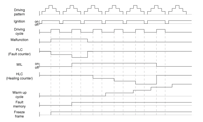
| 1. | When the same malfunction is detected and maintained during two sequential driving cycles, the MIL will automatically illuminate. |
| 2. | The MIL will go off automatically if no fault is detected after 3 sequential driving cycles. |
| 3. | A Diagnostic Trouble Code (DTC) is recorded in ECM memory when a malfunction is detected after two sequential driving cycles. The MIL will illuminate when the malfunction is detected on the second driving cycle. If a misfire is detected, a DTC will be recorded, and the MIL will illuminate, immediately after a fault is first detected. |
| 4. | A Diagnostic Trouble Code (DTC) will automatically erase from ECM memory if the same malfunction is not detected for 40 driving cycles. | •
| A "warm-up cycle" means sufficient vehicle operation such that the coolant temperature has risen by at least 40 degrees Fahrenheit from engine starting and reaches a minimum temperature of 160 degress Fahrenheit. |
| •
| A "driving cycle" consists of engine startup, vehicle operation beyond the beginning of closed loop operation. |
|
|
Components Location1. Engine Control Module (ECM)2. Manifold Absolute Pressure Sensor (MAPS)3. Mass Air Flow Sensor (MAFS)4. Intake Air Temperature Sensor (IATS)5.
ECM Terminal and Input / Output SignalECM Terminal FunctionConnector [C100-A]
Pin No
Description
Connected to
1Injector (Cylinder #3) [Low] control outputInjector (Cylinder #3)2Injector (Cylinder #4) [High] control outputInjector (Cylinder #4)3Injector (Cylinder #3) [Low] control outputInjector (Cylinder #3)4Vehicle speed signal outputCluster5EGR Valve (Motor -)EGR Valve6Sensor power (+5V)Throttle Position Sensor (TPS) 1, 27Sensor power (+5V)EGR Valve8Knock Sensor (KS) signal inputKnock Sensor (KS)9Camshaft Position Sensor (CMPS) [Bank 1 / Exhaust] signal inputCamshaft Position Sensor (CMPS) [Bank 1 / Exhaust]10-11Brake Switch [test] signal inputBrake Switch12Brake Switch [lamp] signal inputBrake Switch13-14-15-16Injector (Cylinder #3) [High] control outputInjector (Cylinder #3)17Injector (Cylinder #1) [High] control outputInjector (Cylinder #1)18Injector (Cylinder #1) [Low] control outputInjector (Cylinder #1)19-20EGR Valve (Motor +)EGR Valve21Sensor shieldKnock Sensor (KS)22Sensor groundKnock Sensor (KS)23-24Sensor groundCamshaft Position Sensor (CMPS) [Bank 1 / Exhaust]25-26-27-28-29-30-31Injector (Cylinder #2) [High] control outputInjector (Cylinder #2) 32-33ETC Motor [-] control outputETC Motor34Sensor groundThrottle Position Sensor (TPS) 1, 235Throttle Position Sensor (TPS) 1 signal inputThrottle Position Sensor (TPS) 136Sensor groundRail Pressure Sensor (RPS)37Rail Pressure Sensor (RPS) signal inputRail Pressure Sensor (RPS)38-39Camshaft Position Sensor (CMPS) [Bank 1 / Intake] signal inputCamshaft Position Sensor (CMPS) [Bank 1 / Intake]40-41-42-43VS-/IP- (Common Ground for VS, IP)Heated Oxygen Sensor [Bank 1 / Sensor 1] 44Rc (Compensative Resistance)Heated Oxygen Sensor [Bank 1 / Sensor 1] 45Sensor groundHeated Oxygen Sensor [Bank 1 / Sensor 2] 46Injector (Cylinder #2) [Low] control outputInjector (Cylinder #2)47-48ETC Motor [+] control outputETC Motor49-50Throttle Position Sensor (TPS) 2 signal inputThrottle Position Sensor (TPS) 251Sensor power (+5V)Rail Pressure Sensor (RPS)52Electrical load signal inputWiper Motor53Sensor groundCamshaft Position Sensor (CMPS) [Bank 1 / Intake]54Sensor groundEGR valve55EGR valve (Feedback signal)EGR valve56-57-58VS+ (NERNST Cell Voltage)Heated Oxygen Sensor [Bank 1 / Sensor 1] 59Rc/Rp (Pump Cell Voltage)Heated Oxygen Sensor [Bank 1 / Sensor 1] 60Heated Oxygen Sensor [Bank 1 / Sensor 2] signal inputHeated Oxygen Sensor [Bank 1 / Sensor 2] Connector [C100-K]
Pin No
Description
Connected to
1ECM GroundChassis Ground2Battery power (B+)Main Relay3ECM GroundChassis Ground4Battery power (B+)Main Relay5ECM GroundChassis Ground6Battery power (B+)Main Relay7Fuel Pressure Control Valve [High] control outputFuel Pressure Control Valve8-9-10Engine Coolant Temperature Sensor (ECTS) signal [EGR Cooler Tube]Engine Coolant Temperature Sensor (ECTS) [EGR Cooler Tube]11Sensor groundEngine Coolant Temperature Sensor (ECTS) [EGR Cooler Tube]12Vehicle speed signal inputIntegrated brake actuation unitSmart key Control Module13-14-15Accelerator Position Sensor (APS) 2 signal inputAccelerator Position Sensor (APS) 216Sensor power (+5V) Accelerator Position Sensor (APS) 217Sensor power (+5V) Manifold Absolute Pressure Sensor (MAPS)18Sensor power (+5V) Accelerator Position Sensor (APS) 119Accelerator Position Sensor (APS) signal inputAccelerator Position Sensor (APS) 120Sensor power (+5V) Crankshaft Position Sensor (CKPS) A/C Pressure Transducer (APT)21-22-23-24Fuel Pump Relay control outputFuel Pump Relay25-26-27-28-29Fuel Pressure Control Valve [Low] control outputFuel Pressure Control Valve30A/C Pressure Transducer (APT) signal inputA/C Pressure Transducer (APT)31-32Crankshaft Position Sensor (CKPS) signal inputCrankshaft Position Sensor (CKPS) 33-34-35-36-37Sensor groundAccelerator Position Sensor (APS) 238Manifold Absolute Pressure Sensor (MAPS) signal inputManifold Absolute Pressure Sensor (MAPS)39Intake Air Temperature Sensor (IATS) signal inputIntake Air Temperature Sensor (IATS)40Sensor groundManifold Absolute Pressure Sensor (MAPS)41Sensor groundAccelerator Position Sensor (APS) 142-43-44Mass Air Flow Sensor (MAFS) signal inputMass Air Flow Sensor (MAFS) 45Sensor groundMass Air Flow Sensor (MAFS) 46Engine Control Relay control outputMain Relay47CVVT Oil control solenoid (OCS) [Bank 1 / Intake] control outputCVVT Oil control solenoid (OCS) [Bank 1 / Intake]48-49-50-51Battery power (B+)Ignition Switch52-53-54Sensor groundCrankshaft Position Sensor (CKPS) 55P-CAN [High]Other control module, Data Link Connector (DLC), Multi-Purpose Check Connetor56H-CAN [High]Other control module, Data Link Connector (DLC), Multi-Purpose Check Connetor57-58Immobilizer communication lineSmart key Control Module59-60Engine Coolant Temperature Sensor (ECTS) signal input [Water Temperature Control Assembly]Engine Coolant Temperature Sensor (ECTS) [Water Temperature Control Assembly]61Sensor groundEngine Coolant Temperature Sensor (ECTS) [Water Temperature Control Assembly]62Fuel Level Sender (FLS) signal inputFuel Level Sender (FLS)63-64Ignition Coil (Cylinder #2) control outputIgnition Coil (Cylinder #2)65Ignition Coil (Cylinder #3) control outputIgnition Coil (Cylinder #3)66-67-68Cooling Fan Relay control outputCooling Fan Relay69-70CVVT Oil Control (OCV) Valve [Bank 1 / Exhaust] control outputCVVT Oil Control Valve (OCV) [Bank 1 / Exhaust] 71- 72- 73Battery power (B+)Battery74- 75Sensor groundA/C Pressure Transducer (APT)76LIN communication signal inputBattery Sensor77P-CAN [Low]Other control module, Data Link Connector (DLC), Multi-Purpose Check Connetor78H-CAN [Low]Other control module, Data Link Connector (DLC), Multi-Purpose Check Connetor79- 80- 81- 82- 838485- 86Ignition Coil (Cylinder #4) control outputIgnition Coil (Cylinder #4)87Ignition Coil (Cylinder #1) control outputIgnition Coil (Cylinder #1)88- 89- 90-91Heated Oxygen Sensor (HO2S) [Bank 1 / Sensor1] Heater control outputHeated Oxygen Sensor (HO2S) [Bank 1 / Sensor 1]92Heated Oxygen Sensor (HO2S) [Bank 1 / Sensor2] Heater control outputHeated Oxygen Sensor (HO2S) [Bank 1 / Sensor 1]93Purge Control Solenoid Valve (PCSV) control outputPurge Control Solenoid Valve (PCSV)94-ECM Terminal Input/Output Signal Connector [C100-A]
Pin No
Description
Condition
Type
Level
1IInjector (Cylinder #3) [Low] control outputRelay OFFDC71VRelay ONMax 1.
Other information:
Description The photo sensor is located at the center of the defrost nozzles.The photo sensor contains a photovoltaic (sensitive to sunlight) diode. The solar radiation received by its light receiving portion, generates an electromotive force in proportion to the amount of radiation received which is transferred to the automatic temperature control
Replacement
When prying with a flat-tip screwdriver or use a prying trim tool, wrap it with protective tape, and apply protective tape around the related parts, to prevent damage.1.Disconnect the negative (-) battery terminal.2.Recover the refrigerant with a recovery / recycling / charging station.

