Hyundai Ioniq (AE): Engine Control System / Engine Control Module (ECM). Schematic diagrams
Hyundai Ioniq (AE) 2017-2022 Service & Repair Manual / Engine Control/Fuel System / Engine Control System / Engine Control Module (ECM). Schematic diagrams
| ECM Terminal and Input / Output Signal |
| ECM Terminal Function |
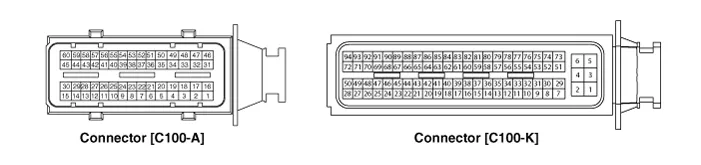
Connector [C100-A]
|
Pin No
|
Description
|
Connected to
|
| 1 | Injector (Cylinder #3) [Low] control output | Injector (Cylinder #3) |
| 2 | Injector (Cylinder #4) [High] control output | Injector (Cylinder #4) |
| 3 | Injector (Cylinder #3) [Low] control output | Injector (Cylinder #3) |
| 4 | Vehicle speed signal output | Cluster |
| 5 | EGR Valve (Motor -) | EGR Valve |
| 6 | Sensor power (+5V) | Throttle Position Sensor (TPS) 1, 2 |
| 7 | Sensor power (+5V) | EGR Valve |
| 8 | Knock Sensor (KS) signal input | Knock Sensor (KS) |
| 9 | Camshaft Position Sensor (CMPS) [Bank 1 / Exhaust] signal input | Camshaft Position Sensor (CMPS) [Bank 1 / Exhaust] |
| 10 | - | |
| 11 | Brake Switch [test] signal input | Brake Switch |
| 12 | Brake Switch [lamp] signal input | Brake Switch |
| 13 | - | |
| 14 | - | |
| 15 | - | |
| 16 | Injector (Cylinder #3) [High] control output | Injector (Cylinder #3) |
| 17 | Injector (Cylinder #1) [High] control output | Injector (Cylinder #1) |
| 18 | Injector (Cylinder #1) [Low] control output | Injector (Cylinder #1) |
| 19 | - | |
| 20 | EGR Valve (Motor +) | EGR Valve |
| 21 | Sensor shield | Knock Sensor (KS) |
| 22 | Sensor ground | Knock Sensor (KS) |
| 23 | - | |
| 24 | Sensor ground | Camshaft Position Sensor (CMPS) [Bank 1 / Exhaust] |
| 25 | - | |
| 26 | - | |
| 27 | - | |
| 28 | - | |
| 29 | - | |
| 30 | - | |
| 31 | Injector (Cylinder #2) [High] control output | Injector (Cylinder #2)  |
| 32 | - | |
| 33 | ETC Motor [-] control output | ETC Motor |
| 34 | Sensor ground | Throttle Position Sensor (TPS) 1, 2 |
| 35 | Throttle Position Sensor (TPS) 1 signal input | Throttle Position Sensor (TPS) 1 |
| 36 | Sensor ground | Rail Pressure Sensor (RPS) |
| 37 | Rail Pressure Sensor (RPS) signal input | Rail Pressure Sensor (RPS) |
| 38 | - | |
| 39 | Camshaft Position Sensor (CMPS) [Bank 1 / Intake] signal input | Camshaft Position Sensor (CMPS) [Bank 1 / Intake] |
| 40 | - | |
| 41 | - | |
| 42 | - | |
| 43 | VS-/IP- (Common Ground for VS, IP) | Heated Oxygen Sensor [Bank 1 / Sensor 1]  |
| 44 | Rc (Compensative Resistance) | Heated Oxygen Sensor [Bank 1 / Sensor 1]  |
| 45 | Sensor ground | Heated Oxygen Sensor [Bank 1 / Sensor 2]  |
| 46 | Injector (Cylinder #2) [Low] control output | Injector (Cylinder #2) |
| 47 | - | |
| 48 | ETC Motor [+] control output | ETC Motor |
| 49 | - | |
| 50 | Throttle Position Sensor (TPS) 2 signal input | Throttle Position Sensor (TPS) 2 |
| 51 | Sensor power (+5V) | Rail Pressure Sensor (RPS) |
| 52 | Electrical load signal input | Wiper Motor |
| 53 | Sensor ground | Camshaft Position Sensor (CMPS) [Bank 1 / Intake] |
| 54 | Sensor ground | EGR valve |
| 55 | EGR valve (Feedback signal) | EGR valve |
| 56 | - | |
| 57 | - | |
| 58 | VS+ (NERNST Cell Voltage) | Heated Oxygen Sensor [Bank 1 / Sensor 1]  |
| 59 | Rc/Rp (Pump Cell Voltage) | Heated Oxygen Sensor [Bank 1 / Sensor 1]  |
| 60 | Heated Oxygen Sensor [Bank 1 / Sensor 2] signal input | Heated Oxygen Sensor [Bank 1 / Sensor 2]  |
Connector [C100-K]
|
Pin No
|
Description
|
Connected to
|
| 1 | ECM Ground | Chassis Ground |
| 2 | Battery power (B+) | Main Relay |
| 3 | ECM Ground | Chassis Ground |
| 4 | Battery power (B+) | Main Relay |
| 5 | ECM Ground | Chassis Ground |
| 6 | Battery power (B+) | Main Relay |
| 7 | Fuel Pressure Control Valve [High] control output | Fuel Pressure Control Valve |
| 8 | - | |
| 9 | - | |
| 10 | Engine Coolant Temperature Sensor (ECTS) signal [EGR Cooler Tube] | Engine Coolant Temperature Sensor (ECTS) [EGR Cooler Tube] |
| 11 | Sensor ground | Engine Coolant Temperature Sensor (ECTS) [EGR Cooler Tube] |
| 12 | Vehicle speed signal input | Integrated brake actuation unit |
| Smart key Control Module | ||
| 13 | - | |
| 14 | - | |
| 15 | Accelerator Position Sensor (APS) 2 signal input | Accelerator Position Sensor (APS) 2 |
| 16 | Sensor power (+5V) | Accelerator Position Sensor (APS) 2 |
| 17 | Sensor power (+5V) | Manifold Absolute Pressure Sensor (MAPS) |
| 18 | Sensor power (+5V) | Accelerator Position Sensor (APS) 1 |
| 19 | Accelerator Position Sensor (APS) signal input | Accelerator Position Sensor (APS) 1 |
| 20 | Sensor power (+5V) | Crankshaft Position Sensor (CKPS) |
| A/C Pressure Transducer (APT) | ||
| 21 | - | |
| 22 | - | |
| 23 | - | |
| 24 | Fuel Pump Relay control output | Fuel Pump Relay |
| 25 | - | |
| 26 | - | |
| 27 | - | |
| 28 | - | |
| 29 | Fuel Pressure Control Valve [Low] control output | Fuel Pressure Control Valve |
| 30 | A/C Pressure Transducer (APT) signal input | A/C Pressure Transducer (APT) |
| 31 | - | |
| 32 | Crankshaft Position Sensor (CKPS) signal input | Crankshaft Position Sensor (CKPS) |
| 33 | - | |
| 34 | - | |
| 35 | - | |
| 36 | - | |
| 37 | Sensor ground | Accelerator Position Sensor (APS) 2 |
| 38 | Manifold Absolute Pressure Sensor (MAPS) signal input | Manifold Absolute Pressure Sensor (MAPS) |
| 39 | Intake Air Temperature Sensor (IATS) signal input | Intake Air Temperature Sensor (IATS) |
| 40 | Sensor ground | Manifold Absolute Pressure Sensor (MAPS) |
| 41 | Sensor ground | Accelerator Position Sensor (APS) 1 |
| 42 | - | |
| 43 | - | |
| 44 | Mass Air Flow Sensor (MAFS) signal input | Mass Air Flow Sensor (MAFS) |
| 45 | Sensor ground | Mass Air Flow Sensor (MAFS) |
| 46 | Engine Control Relay control output | Main Relay |
| 47 | CVVT Oil control solenoid (OCS) [Bank 1 / Intake] control output | CVVT Oil control solenoid (OCS) [Bank 1 / Intake] |
| 48 | - | |
| 49 | - | |
| 50 | - | |
| 51 | Battery power (B+) | Ignition Switch |
| 52 | - | |
| 53 | - | |
| 54 | Sensor ground | Crankshaft Position Sensor (CKPS) |
| 55 | P-CAN [High] | Other control module, Data Link Connector (DLC), Multi-Purpose Check Connetor |
| 56 | H-CAN [High] | Other control module, Data Link Connector (DLC), Multi-Purpose Check Connetor |
| 57 | - | |
| 58 | Immobilizer communication line | Smart key Control Module |
| 59 | - | |
| 60 | Engine Coolant Temperature Sensor (ECTS) signal input [Water Temperature Control Assembly] | Engine Coolant Temperature Sensor (ECTS) [Water Temperature Control Assembly] |
| 61 | Sensor ground | Engine Coolant Temperature Sensor (ECTS) [Water Temperature Control Assembly] |
| 62 | Fuel Level Sender (FLS) signal input | Fuel Level Sender (FLS) |
| 63 | - | |
| 64 | Ignition Coil (Cylinder #2) control output | Ignition Coil (Cylinder #2) |
| 65 | Ignition Coil (Cylinder #3) control output | Ignition Coil (Cylinder #3) |
| 66 | - | |
| 67 | - | |
| 68 | Cooling Fan Relay control output | Cooling Fan Relay |
| 69 | - | |
| 70 | CVVT Oil Control (OCV) Valve [Bank 1 / Exhaust] control output | CVVT Oil Control Valve (OCV) [Bank 1 / Exhaust] |
| 71 | - | |
| 72 | - | |
| 73 | Battery power (B+) | Battery |
| 74 | - | |
| 75 | Sensor ground | A/C Pressure Transducer (APT) |
| 76 | LIN communication signal input | Battery Sensor |
| 77 | P-CAN [Low] | Other control module, Data Link Connector (DLC), Multi-Purpose Check Connetor |
| 78 | H-CAN [Low] | Other control module, Data Link Connector (DLC), Multi-Purpose Check Connetor |
| 79 | - | |
| 80 | - | |
| 81 | - | |
| 82 | - | |
| 83 | ||
| 84 | ||
| 85 | - | |
| 86 | Ignition Coil (Cylinder #4) control output | Ignition Coil (Cylinder #4) |
| 87 | Ignition Coil (Cylinder #1) control output | Ignition Coil (Cylinder #1) |
| 88 | - | |
| 89 | - | |
| 90 | - | |
| 91 | Heated Oxygen Sensor (HO2S) [Bank 1 / Sensor1] Heater control output | Heated Oxygen Sensor (HO2S) [Bank 1 / Sensor 1] |
| 92 | Heated Oxygen Sensor (HO2S) [Bank 1 / Sensor2] Heater control output | Heated Oxygen Sensor (HO2S) [Bank 1 / Sensor 1] |
| 93 | Purge Control Solenoid Valve (PCSV) control output | Purge Control Solenoid Valve (PCSV) |
| 94 | - |
| ECM Terminal Input/Output Signal |
Connector [C100-A]
|
Pin No
|
Description
|
Condition
|
Type
|
Level
|
| 1 | IInjector (Cylinder #3) [Low] control output | Relay OFF | DC | 71V |
| Relay ON | Max 1.0V | |||
| 2 | IInjector (Cylinder #4) [High] control output | Relay ON/OFF | DC | 71V |
| 3 | IInjector (Cylinder #3) [Low] control output | Relay OFF | DC | 71V |
| Relay ON | Max 1.0V | |||
| 4 | Vehicle speed signal output | Idle | Pulse | High : Battery Voltage |
| Low : Max 0.6V | ||||
| 5 | EGR Valve (Motor -) | |||
| 6 | Sensor power (+5V) | IG OFF | DC | Max 0.5V |
| IG ON | 4.9 - 5.1V | |||
| 7 | Sensor power (+5V) | IG OFF | DC | Max 50 mV |
| IG ON | 4.9 - 5.1V | |||
| 8 | Knock Sensor (KS) signal input | Knocking | Variable Frequency | -0.3 to 0.3V |
| Normal | 0V | |||
| 9 | Camshaft Position Sensor (CMPS) [Bank 1 / Exhaust] signal input | Engine Run | Pulse | High : 4.5 - 5.5V |
| Low : -0.3 to 0.5V | ||||
| Frequency : 7 Hz (Idle), 25 Hz (3,000 rpm) | ||||
| 10 | - | |||
| 11 | Brake Switch [test] signal input | Brake OFF | DC | Battery Voltage (B+) |
| Brake ON | Max 50 mV | |||
| 12 | Brake Switch [lamp] signal input | Brake OFF | DC | Max 50 mV |
| Brake ON | Battery Voltage (B+) | |||
| 13 | - | |||
| 14 | - | |||
| 15 | - | |||
| 16 | IInjector (Cylinder #3) [High] control output | Relay ON/OFF | DC | 71V |
| 17 | IInjector (Cylinder #1) [High] control output | Relay ON/OFF | DC | 71V |
| 18 | IInjector (Cylinder #1) [Low] control output | Relay OFF | DC | 71V |
| Relay ON | Max 1.0V | |||
| 19 | - | |||
| 20 | EGR Valve (Motor +) | |||
| 21 | Sensor shield | Idle | DC | Max 50 mV |
| 22 | Sensor ground | Idle | DC | Max 50 mV |
| 23 | - | |||
| 24 | Sensor ground | Idle | DC | Max 50 mV |
| 25 | - | |||
| 26 | - | |||
| 27 | - | |||
| 28 | - | |||
| 29 | - | |||
| 30 | - | |||
| 31 | IInjector (Cylinder #2) [High] control output | Relay ON/OFF | DC | 71V |
| 32 | - | |||
| 33 | ETC Motor [-] control output | |||
| 34 | Sensor ground | Idle | DC | Max 50 mV |
| 35 | Throttle Position Sensor (TPS) 1 signal input | C.T | Analog | 0.3 - 0.9V |
| W.O.T | 1.5 - 3.0V | |||
| 36 | Sensor ground | Idle | DC | Max 50 mV |
| 37 | Rail Pressure Sensor (RPS) signal input | Idle | Analog | -0.3 to 5.2V |
| 38 | - | |||
| 39 | Camshaft Position Sensor (CMPS) [Bank 1 / Intake] signal input | Engine Run | Pulse | High : 4.5 - 5.5V |
| Low : -0.3 to 0.5V | ||||
| Frequency : 7 Hz (Idle), 25 Hz (3,000 rpm) | ||||
| 40 | - | |||
| 41 | - | |||
| 42 | - | |||
| 43 | VS-/IP- (Common Ground for VS, IP) | Idle | Analog | Reference for V_IP, V_N |
| 44 | Rc (Compensative Resistance) | Idle | Analog | │Rc-Rc/Rp│< ±0.1V |
| 45 | Sensor ground | Idle | DC | Max 50 mV |
| 46 | IInjector (Cylinder #2) [Low] control output | Relay OFF | DC | 71V |
| Relay ON | Max 1.0V | |||
| 47 | - | |||
| 48 | ETC Motor [+] control output | Engine Run | Pulse | High : Battery Voltage (B+) |
| Low : Max1.0V | ||||
| 49 | - | |||
| 50 | Throttle Position Sensor (TPS) 2 signal input | C.T | Analog | 4.2 - 5.0V |
| W.O.T | 3.3 - 3.8V | |||
| 51 | Sensor power (+5V) | IG OFF | DC | Max 50 mV |
| IG ON | 4.9 - 5.1V | |||
| 52 | Electrical load signal input | Lamp OFF | DC | Battery Voltage (B+) |
| Lamp ON | Max 50 mV | |||
| 53 | Sensor ground | Idle | DC | Max 50 mV |
| 54 | Sensor ground | Idle | DC | Max 50 mV |
| 55 | EGR valve (Feedback signal) | |||
| 56 | - | |||
| 57 | - | |||
| 58 | VS+ (NERNST Cell Voltage) | Idle | Analog | Normal : 450 ± 50 mV |
| Rich : Max Normal+150 mV | ||||
| Lean : Min Normal-150 mV | ||||
| 59 | Rc/Rp (Pump Cell Voltage) | Idle | Analog | Normal : 450 ± 50 mV |
| Rich : Max Normal+150 mV | ||||
| Lean : Min Normal-150 mV | ||||
| 60 | Heated Oxygen Sensor [Bank 1 / Sensor 2] signal input | Idle | DC | Rich : 0.6 - 1.0V |
| Lean : Max 0.4V |
Connector [C100-K]
|
Pin No
|
Description
|
Condition
|
Type
|
Level
|
| 1 | ECM Ground | Idle | DC | -0.3 to 0.5V |
| 2 | Battery power (B+) | IG OFF | DC | Max 1.0V |
| IG ON | Battery Voltage (B+) | |||
| 3 | ECM Ground | Idle | DC | -0.3 to 0.5V |
| 4 | Battery power (B+) | IG OFF | DC | Max 1.0V |
| IG ON | Battery Voltage (B+) | |||
| 5 | ECM Ground | Idle | DC | -0.3 to 0.5V |
| 6 | Battery power (B+) | IG OFF | DC | Max 1.0V |
| IG ON | Battery Voltage (B+) | |||
| 7 | Fuel Pressure Control Valve [High] control output | Engine Run | PWM |
|
| 8 | - | |||
| 9 | - | |||
| 10 | Engine Coolant Temperature Sensor (ECTS) signal [EGR Cooler Tube] | Idle | Analog | 0.5 - 4.5V |
| (Idle : 1.02V) | ||||
| 11 | Sensor ground | Idle | DC | Max 50 mV |
| 12 | Vehicle speed signal input | |||
| 13 | - | |||
| 14 | - | |||
| 15 | Accelerator Position Sensor (APS) 2 signal input | C.T | Analog | Max 1.0V |
| W.O.T | 1.5 - 3.0V | |||
| 16 | Sensor power (+5V) | IG OFF | DC | Max 50 mV |
| IG ON | 4.9 - 5.1V | |||
| 17 | Sensor power (+5V) | IG OFF | DC | Max 50 mV |
| IG ON | 4.9 - 5.1V | |||
| 18 | Sensor power (+5V) | IG OFF | DC | Max 50 mV |
| IG ON | 4.9 - 5.1V | |||
| 19 | Accelerator Position Sensor (APS) signal input | C.T | Analog | Max 1.0V |
| W.O.T | Min 4.0V | |||
| 20 | Sensor power (+5V) | IG OFF | DC | Max 50 mV |
| IG ON | 4.9 - 5.1V | |||
| 21 | - | |||
| 22 | - | |||
| 23 | - | |||
| 24 | Fuel Pump Relay control output | Relay OFF | DC | Battery Voltage (B+) |
| Relay ON | -0.3 to 1.2V | |||
| 25 | - | |||
| 26 | - | |||
| 27 | - | |||
| 28 | - | |||
| 29 | Fuel Pressure Control Valve [Low] control output | Engine Run | PWM |
|
| 30 | A/C Pressure Transducer (APT) signal input | A/C ON | Analog | 0.348 - 4.63 V |
| 31 | - | |||
| 32 | Crankshaft Position Sensor (CKPS) signal input | Engine Run | Pulse | High : 4.5 - 5.5V |
| Low : -0.3 to 0.5V | ||||
| Frequency : 850 Hz (Idle), 3,000 Hz (3,000 rpm) | ||||
| 33 | - | |||
| 34 | - | |||
| 35 | - | |||
| 36 | - | |||
| 37 | Sensor ground | Idle | DC | Max 50 mV |
| 38 | Manifold Absolute Pressure Sensor (MAPS) signal input | Idle | Analog | 0.8 - 1.6V (Idle : 1.37V) |
| 39 | Intake Air Temperature Sensor (IATS) signal input | Idle | Analog | 0 - 5.0V (Idle : 2.55V) |
| 40 | Sensor ground | Idle | DC | Max 50 mV |
| 41 | Sensor ground | Idle | DC | Max 50 mV |
| 42 | - | |||
| 43 | - | |||
| 44 | Mass Air Flow Sensor (MAFS) signal input | |||
| 45 | Sensor ground | Idle | DC | Max 50 mV |
| 46 | Engine Control Relay control output | Relay OFF | DC | Battery Voltage (B+) |
| Relay ON | -0.3 to 1.2V | |||
| 47 | CVVT Oil control solenoid (OCS) [Bank 1 / Intake] control output | |||
| 48 | - | |||
| 49 | - | |||
| 50 | - | |||
| 51 | Battery power (B+) | IG OFF | DC | Max 1.0V |
| IG ON | Battery Voltage (B+) | |||
| 52 | - | |||
| 53 | - | |||
| 54 | Sensor ground | Idle | DC | Max 50 mV |
| 55 | P-CAN [High] | Recessive | Pulse | 2.0 - 3.0V |
| Dominant | 2.75 - 4.5V | |||
| 56 | H-CAN [High] | Recessive | Pulse | 2.0 - 3.0V |
| Dominant | 2.75 - 4.5V | |||
| 57 | - | |||
| 58 | Immobilizer communication line | |||
| 59 | - | |||
| 60 | Engine Coolant Temperature Sensor (ECTS) signal input [Water Temperature Control Assembly] | |||
| 61 | Sensor ground | Idle | DC | Max 50 mV |
| 62 | Fuel Level Sender (FLS) signal input | Idle | Analog | 0.55 - 4.37V |
| 63 | - | |||
| 64 | Ignition Coil (Cylinder #2) control output | Engine Run | Pulse | Vpeak = 360 - 440V |
| 125 |


DescriptionIf the Gasoline Engine Control system components (sensors, ECM, injector, etc.) fail, interruption to the fuel supply or failure to supply the proper amount of fuel for various engine operating conditions will result.
Removal • When replacing the ECM, the vehicle equipped with the immobilizer must be performed procedure as below.
Categories
- Manuals Home
- Hyundai Ioniq Owners Manual
- Hyundai Ioniq Service Manual
- Repair procedures
- Checking the Coolant Level
- Hybrid Vehicle Engine Compartment
- New on site
- Most important about car

Copyright © 2026 www.hioniqae.com - 0.0116