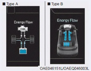
Hyundai Ioniq (AE): Driving the Hybrid/Plug-in Hybrid Vehicle / Energy flow
The hybrid system informs the drivers its energy flow in various operating modes. While driving, the current energy flow is specified in 11 modes.
Vehicle Stop
The vehicle is stopped. (No energy flow)
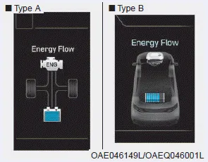
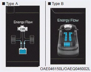
EV Propulsion
Only the motor power is used to drive the vehicle.
(Battery âžž Wheel)
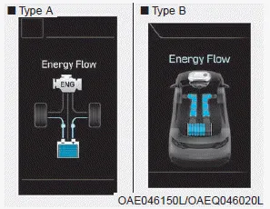
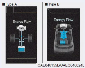
Power Assist

Both the motor and the engine power are used to drive the vehicle.
(Battery & Energy âžž Wheel)
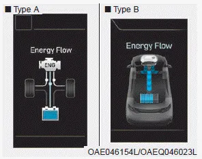
Engine Only Propulsion
Only the engine power is used to drive the vehicle.
(Engine âžž Wheel)
Engine Generation
When the vehicle is stopped, the high-voltage battery is charged up by the engine.
(Engine âžž Battery)
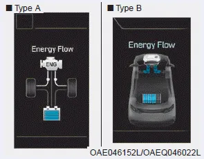
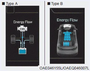
Regeneration
The high-voltage battery is charged up by the regenerative brake system.
(Wheel âžž Battery)
Engine Brake

The engine braking is used to decelerate the vehicle.
(Wheel âžž Engine)
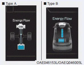
Power Reserve
The engine is simultaneously used to drive the vehicle and to charge up the high-voltage battery.
(Engine âžž Wheel & Battery)
Engine Generation/Motor Drive
The engine charges up the high-voltage battery. The motor power is used to drive the vehicle.
(Engine âžž Battery âžž Wheel)
Engine Generation/Regeneration
The engine and regenerative brake system charges up the high-voltage battery.
(Engine & Wheel âžž Battery)
Engine Brake/Regeneration
The engine braking is simultaneously used to decelerate the vehicle and to charge up the high-voltage battery.
(Wheel âžž Engine & Battery)
Check Hybrid system This message is displayed when there is a problem with the hybrid control system. Refrain from driving when the warning message is displayed.
Other information:
Hyundai Ioniq (AE) 2017-2022 Service & Repair Manual: Evaporator Temperature Sensor. Description and operation
DescriptionThe evaporator temperature sensor will detect the evaporator core temperature and interrupt compressor relay power in order to prevent evaporator from freezing by excessive cooling. The evaporator temperature sensor has the Negative Temperature Coefficient (NTC).
Hyundai Ioniq (AE) 2017-2022 Service & Repair Manual: Photo Sensor. Repair procedures
Inspection1.Turn the ignition switch ON.2.Connect the GDS.3.Emit intensive light toward the photo sensor using a lamp, and check the output voltage change.4.The voltage will rise with higher intensive light and reduce with lower intensive light.1. Auto light signal2.
Categories
- Manuals Home
- Hyundai Ioniq Owners Manual
- Hyundai Ioniq Service Manual
- Heating, Ventilation and Air Conditioning
- Brake System
- Maintenance
- New on site
- Most important about car
