Hyundai Ioniq (AE): Crash Pad / Glove Box. Repair procedures
Hyundai Ioniq (AE) 2017-2022 Service & Repair Manual / Body (Interior and Exterior) / Crash Pad / Glove Box. Repair procedures
| Replacement |
|

| 1. | Remove both stoppers (B) from the glove box (A) by turning the stoppers.
|
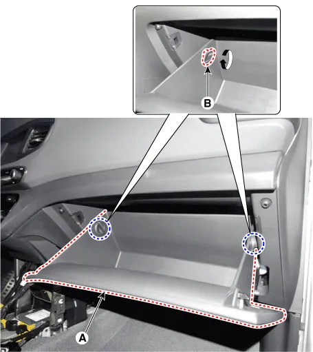
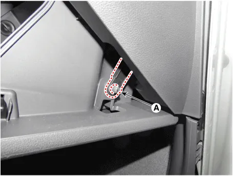
| 2. | Separate the air damper from the glove box (A).
|
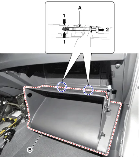
| 3. | Disconnect the pushpins (A) and then remove the glove box (B).
|
| 4. | To install, reverse the removal procedure.
|

Component Location 1. Glove box
Component Location 1. Glove box upper cover assembly
Other information:
Hyundai Ioniq (AE) 2017-2022 Service & Repair Manual: Photo Sensor. Description and operation
Description The photo sensor is located at the center of the defrost nozzles.The photo sensor contains a photovoltaic (sensitive to sunlight) diode. The solar radiation received by its light receiving portion, generates an electromotive force in proportion to the amount of radiation received which is transferred to the automatic temperature control
Hyundai Ioniq (AE) 2017-2022 Service & Repair Manual: PTC Heater. Description and operation
DescriptionThe PTC (Positive Temperature Coefficient) heater is installed at the exit or the backside of the heater core.The PTC heater is an electric heater using a PTC element as an auxiliary heating device that supplements deficiency of interior heat source in highly effective hybrid engine.
Categories
- Manuals Home
- Hyundai Ioniq Owners Manual
- Hyundai Ioniq Service Manual
- Hybrid Vehicle Engine Compartment
- Engine Control/Fuel System
- If the 12 Volt Battery is Discharged (Hybrid Vehicle)
- New on site
- Most important about car

Copyright © 2026 www.hioniqae.com - 0.0136