Hyundai Ioniq (AE): Head Lamp Leveling Device / Head Lamp Leveling Switch. Repair procedures
Hyundai Ioniq (AE) 2017-2022 Service & Repair Manual / Body Electrical System / Head Lamp Leveling Device / Head Lamp Leveling Switch. Repair procedures
| Inspection |
| 1. | Disconnect the negative (-) battery terminal. |
| 2. | Remove the crash pad lower panel (A). (Refer to Body - "Crash Pad Lower Panel")
|
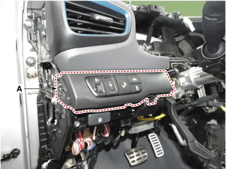
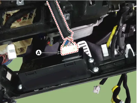
| 3. | Disconnect the rheostat switch connector (A).
|
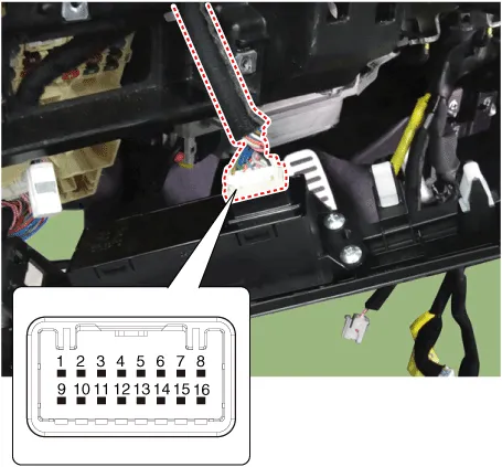
| 4. | Operate the BSD switch, then check for continuity between terminals of BSD switch connector.
|
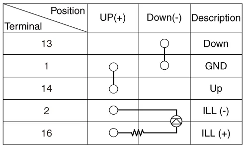
SCHEMATIC DIAGRAM
Other information:
Hyundai Ioniq (AE) 2017-2022 Service & Repair Manual: Mode Control Actuator. Specifications
S
Hyundai Ioniq (AE) 2017-2022 Service & Repair Manual: Front View Camera Unit. Repair procedures
Removal1.Disconnect the negative (-) battery terminal.2.Remove the front view camera cover (A).3.Disconnect the front view camera connector (A).4.Remove the front view camera after disengaging the mounting bracket (A).Installation1.Align front view camera with windshield bracket using forward edge point (A).
Categories
- Manuals Home
- Hyundai Ioniq Owners Manual
- Hyundai Ioniq Service Manual
- How to Connect Portable Charger (ICCB: In-Cable Control Box)
- Maintenance
- Theft-alarm System
- New on site
- Most important about car

Copyright © 2026 www.hioniqae.com - 0.0223