Hyundai Ioniq (AE): Fuses And Relays / Relay Box (Engine Compartment). Repair procedures
| Inspection |
| 1. | Disconnect the negative (-) battery terminal. |
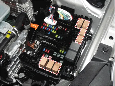
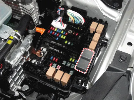
| 2. | Pull out the relay from the engine compartment relay block. |
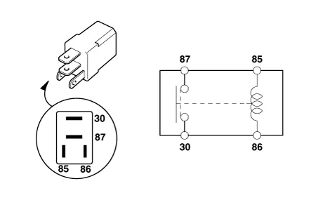
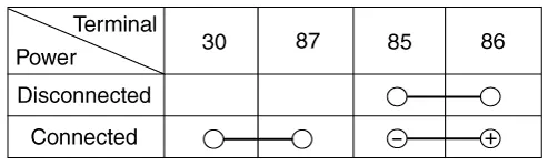
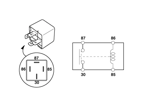
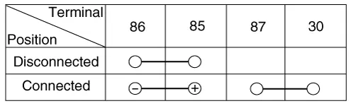
| 1. | After supplying power to between No. 85 and 86 power relay terminals, check that there is continuity between No. 30 and 87 terminals. |
| 2. | After disconnecting power between No. 85 and 86 power relay terminals, check that there is no continuity between No. 30 and 87 terminals. Engine Room Relay Block
|
| 1. | After supplying power to between No. 85 and 86 power relay terminals, check that there is continuity between No. 30 and 87 terminals. |
| 2. | After disconnecting power between No. 85 and 86 power relay terminals, check that there is no continuity between No. 30 and 87 terminals.
|
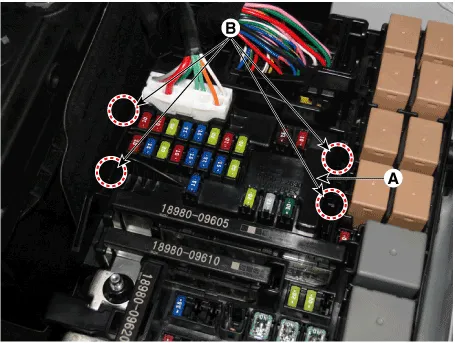
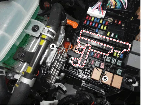
| 1. | Disconnect the negative (-) battery terminal. |
| 2. | Push the four hooks (B) in the direction of the arrow and lift up the PCB block (A).
|
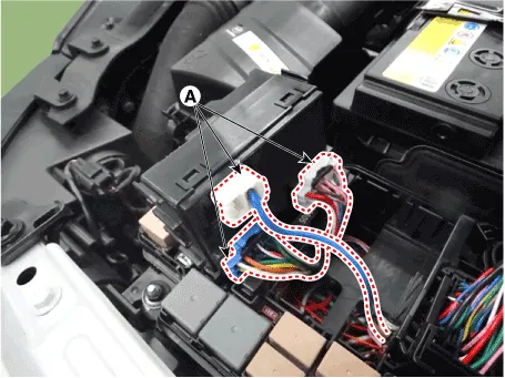
| 3. | Remove the PCB block by disconnet the connector.
|
| 1. | Check that the fuse holders are loosely held and that the fuses are securely fixed by the holders. |
| 2. | Check that each fuse circuit has the exact fuse capacity. |
| 3. | Check the fuses for any damage.
|

|

Component LocationEngine Room Junction BlockE/R Junction BlockCircuit (E/R Junction Block)Metal Core Block (PCB)PCB BlockCircuit (PCB Block)
Component LocationInterior Junction BlockIGPMCircuit (IGPM)
Other information:
Hyundai Ioniq (AE) 2017-2022 Service & Repair Manual: Front View Camera Unit. Repair procedures
Removal1.Disconnect the negative (-) battery terminal.2.Remove the front view camera cover (A).3.Disconnect the front view camera connector (A).4.Remove the front view camera after disengaging the mounting bracket (A).Installation1.Align front view camera with windshield bracket using forward edge point (A).
Hyundai Ioniq (AE) 2017-2022 Service & Repair Manual: Description and operation
Cruise ControlThe cruise control system is engaged by the cruise "ON/OFF" main switch located on right of steering wheel column. The system has the capability to cruise, coast, accelerate and resume speed.It also has a safety interrupt, engaged upon depressing brake or shifting select lever.
Categories
- Manuals Home
- Hyundai Ioniq Owners Manual
- Hyundai Ioniq Service Manual
- Repair procedures
- DCT(Dual Clutch Transmission) System
- If the 12 Volt Battery is Discharged (Hybrid Vehicle)
- New on site
- Most important about car
