Hyundai Ioniq (AE): Fuses And Relays / Relay Box (Passenger Compartment). Components and components location
| Component Location |
| IGPM |
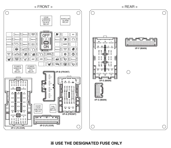
| Circuit (IGPM) |

Inspection1.Disconnect the negative (-) battery terminal.2.Pull out the relay from the engine compartment relay block.Power Relay (Type A) Check for continuity between the terminals.
DescriptionAuto Cut System of Dark Current Abbreviation Expalnation AAFActive Air FlapACUAirbag Control UnitAEBAutonomous Emergency BrakingAHBActive Hybrid Brake SystemAMPAmplifierAVNHead Unit (Audio / AVN)B_CANBody Controller Area NetworkBCMBody Control ModuleBMSBattery Management SystemBSDBlind Spot DetectionC_CANChassis Controller Area NetworkCARMERARear View CarmeraCLUCluster ModuleDATCDual Automatic Temp ControlFPCMFuel Pump Control ModuleHPCUHybrid Power UnitIGPMIntergrated Gateway & Power control ModuleLDWSLane Departure Warning SystemM_CANMulti media Controller Area NetworkMDPSMotor Driven Power SteeringP_CANPowertrain Controller Area NetworkPASParking Assist SystemSJBSmart Junction BlockSMKSmart Key UnitTCM(DCT)Double Clutch Transmission UnitVESSVirtual Engine Sound SystemSmart Junction Block (SJB) General function : Interior Junction Block + some functions of BCMIt controls loads with CAN communication and IPS.
Other information:
Hyundai Ioniq (AE) 2017-2022 Service & Repair Manual: Photo Sensor. Repair procedures
Inspection1.Turn the ignition switch ON.2.Connect the GDS.3.Emit intensive light toward the photo sensor using a lamp, and check the output voltage change.4.The voltage will rise with higher intensive light and reduce with lower intensive light.1. Auto light signal2.
Hyundai Ioniq (AE) 2017-2022 Service & Repair Manual: Smart Cruise Control (SCC) Switch. Repair procedures
Removal1.Disconnect the negative (-) battery terminal.2.Remove the steering wheel assembly.(Refer to Steering System -"Steering Wheel")3.Remove the steering back cover (A).4.Remove the steering remote control connector (A).5.Remove the steering remote control (A), after loosening the screws.
Categories
- Manuals Home
- Hyundai Ioniq Owners Manual
- Hyundai Ioniq Service Manual
- DCT(Dual Clutch Transmission) System
- Engine Clutch System
- Engine Mechanical System
- New on site
- Most important about car
