Hyundai Ioniq (AE): Fuses And Relays / Relay Box (Engine Compartment). Repair procedures
| Inspection |
| 1. | Disconnect the negative (-) battery terminal. |
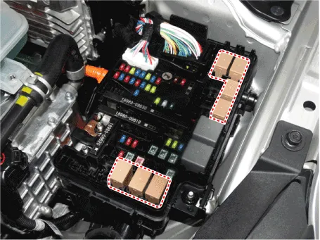
| 2. | Pull out the relay from the engine compartment relay block. |
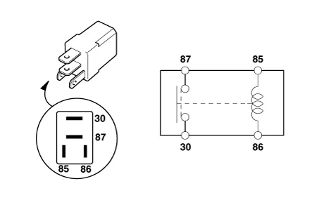
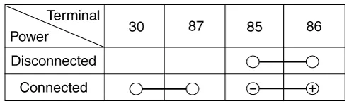
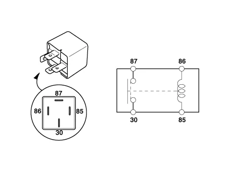
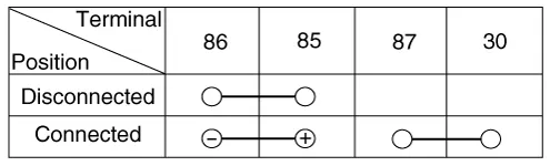
| 1. | After supplying power to between No. 85 and 86 power relay terminals, check that there is continuity between No. 30 and 87 terminals. |
| 2. | After disconnecting power between No. 85 and 86 power relay terminals, check that there is no continuity between No. 30 and 87 terminals. Engine Room Relay Block
|
| 1. | After supplying power to between No. 85 and 86 power relay terminals, check that there is continuity between No. 30 and 87 terminals. |
| 2. | After disconnecting power between No. 85 and 86 power relay terminals, check that there is no continuity between No. 30 and 87 terminals.
|
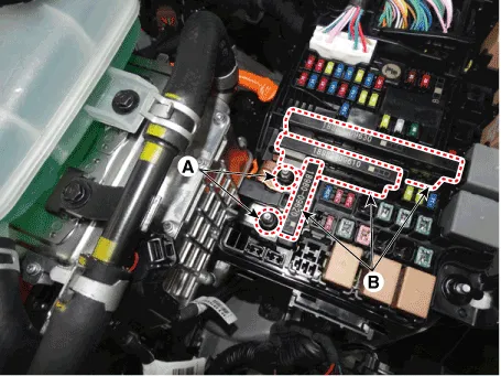
| 1. | Disconnect the negative (-) battery terminal. |
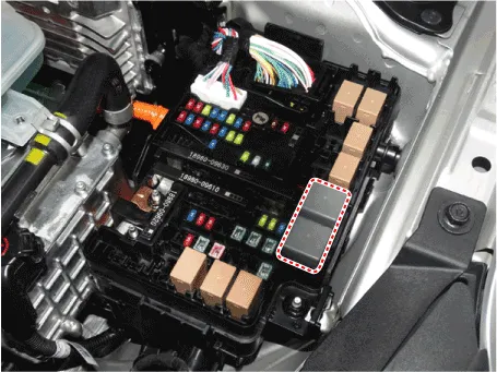
| 2. | Push the four hooks (B) in the direction of the arrow and lift up the PCB block (A).
|
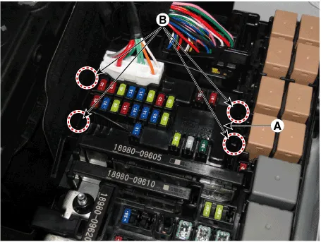
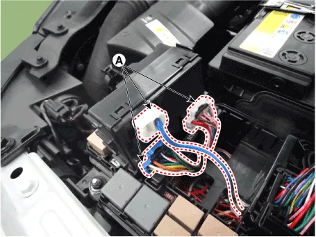
| 3. | Remove the PCB block by disconnet the connector.
|
| 1. | Check that the fuse holders are loosely held and that the fuses are securely fixed by the holders. |
| 2. | Check that each fuse circuit has the exact fuse capacity. |
| 3. | Check the fuses for any damage.
|

|

Component LocationEngine Room Junction BlockE/R Junction BlockCircuit (E/R Junction Block)Metal Core Block (PCB)PCB BlockCircuit (PCB Block)
Component LocationInterior Junction BlockIGPMCircuit (IGPM)
Other information:
Hyundai Ioniq (AE) 2017-2022 Service & Repair Manual: Mode Control Actuator. Description and operation
DescriptionThe mode control actuator is located at the heater unit.It adjusts the position of the mode door by operating the mode control actuator based on the signal of the A/C control unit. Pressing the mode select switch makes the mode control actuator shift in order of Vent → Bi-Level → Floor → Mix.
Hyundai Ioniq (AE) 2017-2022 Service & Repair Manual: General safety information and caution
Safety PrecautionPrecautions To Take Before Servicing High Voltage System • Since hybrid vehicles contain a high voltage battery, if the high voltage system or vehicles are handled incorrectly, this might lead to a serious accidents like electric shock and electric leakage.
Categories
- Manuals Home
- Hyundai Ioniq Owners Manual
- Hyundai Ioniq Service Manual
- If the 12 Volt Battery is Discharged (Hybrid Vehicle)
- Engine Clutch System
- Heating, Ventilation and Air Conditioning
- New on site
- Most important about car
