Hyundai Ioniq (AE): Rail Pressure Sensor (RPS) / Schematic diagrams
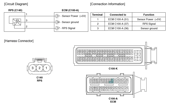
| Circuit Diagram |
Signal Waveform
Inspection1.Connect the GDS on the Data Link Connector (DLC).2.Measure the output voltage of the RPS at idle and various engine speed. Condition Output Voltage (V) Idle Approx.
Other information:
Hyundai Ioniq (AE) 2017-2022 Service & Repair Manual: emperature Control Actuator. Specifications
S
Hyundai Ioniq (AE) 2017-2022 Service & Repair Manual: Description and operation
DescriptionThe smart cruise control system allows a driver to program the vehicle to control the speed and following distance by detecting the vehicle ahead without depressing the brake pedal and the accelerator pedal.1.Cruise speed control : The vehicle maintains the selected speed if there are not vehicles ahead.
Categories
- Manuals Home
- Hyundai Ioniq Owners Manual
- Hyundai Ioniq Service Manual
- Engine Clutch System
- Hybrid Vehicle Engine Compartment
- Suspension System
- New on site
- Most important about car

Copyright © 2026 www.hioniqae.com - 0.018