Hyundai Ioniq (AE): Rail Pressure Sensor (RPS) / Repair procedures
| Inspection |
| 1. | Connect the GDS on the Data Link Connector (DLC). |
| 2. | Measure the output voltage of the RPS at idle and various engine speed.
|
| Removal |
| 1. | Turn the ignition switch OFF and disconnect the battery negative (-) cable. |
| 2. | Release the residual pressure in fuel line. (Refer to Fuel Delivery System - "Release Residual Pressure in Fuel Line")
|

| 3. | Remove the intake manifold. (Refer to Engine Mechanical System - "Intake Manifold") |
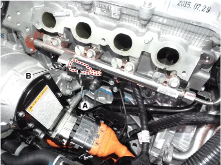
| 4. | Disconnect the rail pressure sensor connector (A), and then remove the sensor (B) from the delivery pipe.
|
| Installation |
|
| 1. | Install in the reverse order of removal.
|
Circuit Diagram
DescriptionAccelerator Position Sensor (APS) is installed on the accelerator pedal module and detects the rotation angle of the accelerator pedal. The APS is one of the most important sensors in engine control system, so it consists of the two sensors which adapt individual sensor power and ground line.
Categories
- Manuals Home
- Hyundai Ioniq Owners Manual
- Hyundai Ioniq Service Manual
- Body (Interior and Exterior)
- Jump Starting
- Theft-alarm System
- New on site
- Most important about car

Copyright © 2026 www.hioniqae.com - 0.0126