Hyundai Ioniq (AE): Rail Pressure Sensor (RPS) / Schematic diagrams
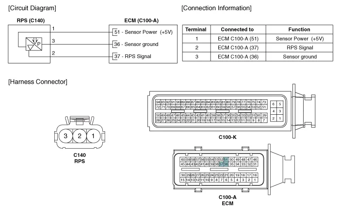
| Circuit Diagram |
Signal Waveform
Inspection1.Connect the GDS on the Data Link Connector (DLC).2.Measure the output voltage of the RPS at idle and various engine speed. Condition Output Voltage (V) Idle Approx.
Other information:
Hyundai Ioniq (AE) 2017-2022 Service & Repair Manual: Warning Indicator. Components and components location
C
Hyundai Ioniq (AE) 2017-2022 Service & Repair Manual: Cruise Control Switch. Repair procedures
Removal1.Disconnect the negative (-) battery terminal.2.Remove the steering wheel assembly.(Refer to Steering System - "Steering Wheel")3.Remove the steering back cover (A).4.Remove the steering remote control connector (A).5.Remove the steering remote control after loosening the screws.
Categories
- Manuals Home
- Hyundai Ioniq Owners Manual
- Hyundai Ioniq Service Manual
- Body (Interior and Exterior)
- DCT(Dual Clutch Transmission) System
- Hybrid Vehicle Engine Compartment
- New on site
- Most important about car

Copyright © 2026 www.hioniqae.com - 0.0109