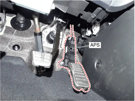
Hyundai Ioniq (AE): Engine Control System / Accelerator Position Sensor (APS). Description and operation
| Description |
Inspection1.Connect the GDS on the Data Link Connector (DLC).2.Measure the output voltage of the RPS at idle and various engine speed. Condition Output Voltage (V) Idle Approx.
Specification Accelerator Position Output Voltage (V) APS1 APS2 C.
Other information:
Hyundai Ioniq (AE) 2017-2022 Service & Repair Manual: emperature Control Actuator. Description and operation
DescriptionThe temperature control actuator is located at the heater unit. It regulates the temperature by the procedure as follows. The signal from the control unit adjusts the position of the temperature door by operating the temperature switch. Then the temperature will be regulated by the hot/cold air ratio decided by the position of the temper
Hyundai Ioniq (AE) 2017-2022 Service & Repair Manual: Cruise Control Switch. Components and components location
C
Categories
- Manuals Home
- Hyundai Ioniq Owners Manual
- Hyundai Ioniq Service Manual
- Transmission Gear Oil. Repair procedures
- Engine Clutch System
- If the 12 Volt Battery is Discharged (Hybrid Vehicle)
- New on site
- Most important about car
