Hyundai Ioniq (AE): Engine Control System / Accelerator Position Sensor (APS). Specifications
| Specification |
|
Accelerator Position
|
Output Voltage (V)
| |
|
APS1
|
APS2
| |
| C.T | 0.7 - 0.8 | 0.325 - 0.425 |
| W.O.T | 3.98 - 4.22 | 1.98 - 2.13 |
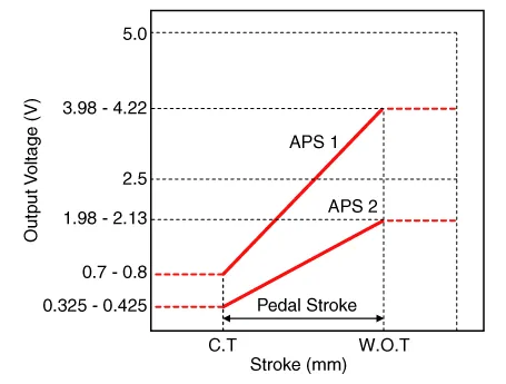
DescriptionAccelerator Position Sensor (APS) is installed on the accelerator pedal module and detects the rotation angle of the accelerator pedal. The APS is one of the most important sensors in engine control system, so it consists of the two sensors which adapt individual sensor power and ground line.
Circuit Diagram
Other information:
Hyundai Ioniq (AE) 2017-2022 Service & Repair Manual: Ambient Temperature Sensor. Description and operation
DescriptionThe ambient temperature sensor is located at the front of the condenser and detects ambient air temperature. It is a negative type thermistor; resistance will increase with lower temperature, and decrease with higher temperature.The sensor output will be used for discharge temperature control, temperature regulation door contrl, blower m
Hyundai Ioniq (AE) 2017-2022 Service & Repair Manual: Parking Distance Warning (PDW) Sensor. Repair procedures
Removal1.Disconnect the negative (-) battery terminal.2.Remove the front / rear bumper cover.(Refer to Body - "Front Bumper Cover")(Refer to Body - "Rear Bumper Cover")3.Disconnect the connector (A) from the parking assist sensor.4.Remove the sensor (A) by pulling out both ends of the sensor holder.
Categories
- Manuals Home
- Hyundai Ioniq Owners Manual
- Hyundai Ioniq Service Manual
- Body (Interior and Exterior)
- Jump Starting
- Heating, Ventilation and Air Conditioning
- New on site
- Most important about car
