Hyundai Ioniq (AE): Engine Control System / Accelerator Position Sensor (APS). Schematic diagrams
| Circuit Diagram |
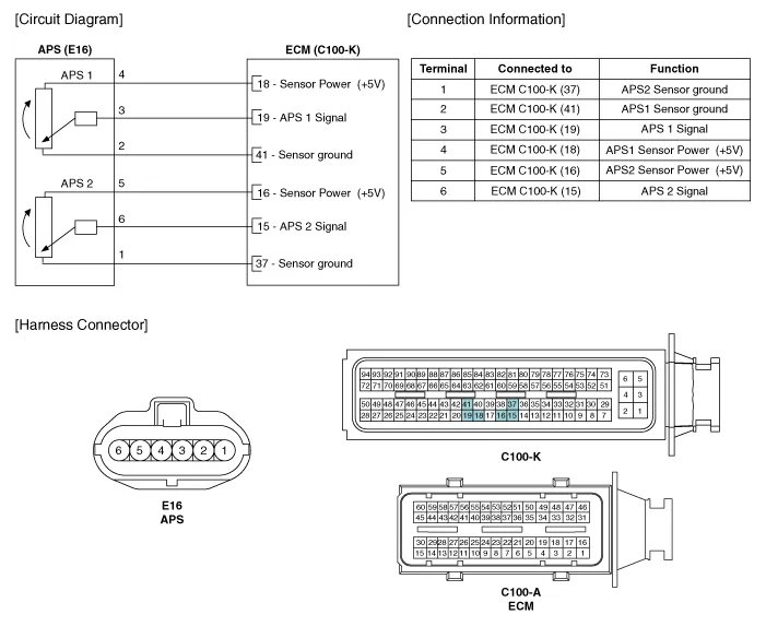
Specification Accelerator Position Output Voltage (V) APS1 APS2 C.
Inspection1.Connect the GDS on the Data Link Connector (DLC).2.Turn the ignition switch ON.3.Measure the output voltage of the APS 1 and 2 at C.T and W.
Other information:
Hyundai Ioniq (AE) 2017-2022 Service & Repair Manual: Climate Control Air Filter. Repair procedures
Replacement1.Disconnect the air damper (A) from the glove box (B).2.Remove the stopper (B) from the glove box (A).3.Remove the filter cover (A) by pressing the knob.4.Replace the air filter (A) with a new one according to the direction of air filter. • To remove the filter easily, press the right side inwa
Hyundai Ioniq (AE) 2017-2022 Service & Repair Manual: Warning Indicator. Repair procedures
RemovalWarning Indicator1.Disconnect the negative (-) battery terminal.2.Remove the mirror (A).InstallationWarning Indicator1.Install the outside mirror.2.Connect the negative (-) battery terminal.Inspection1.Apply battery voltage to each terminal as shown in the table and verify that the mirror operates properly.
Categories
- Manuals Home
- Hyundai Ioniq Owners Manual
- Hyundai Ioniq Service Manual
- Body (Interior and Exterior)
- Jump starting procedure
- Theft-alarm System
- New on site
- Most important about car
