Hyundai Ioniq (AE): Front Radar System / Smart Cruise Control (SCC) Switch. Repair procedures
Hyundai Ioniq (AE) 2017-2022 Service & Repair Manual / Advanced Driver Assistance System (ADAS) / Front Radar System / Smart Cruise Control (SCC) Switch. Repair procedures
| Removal |
| 1. | Disconnect the negative (-) battery terminal. |
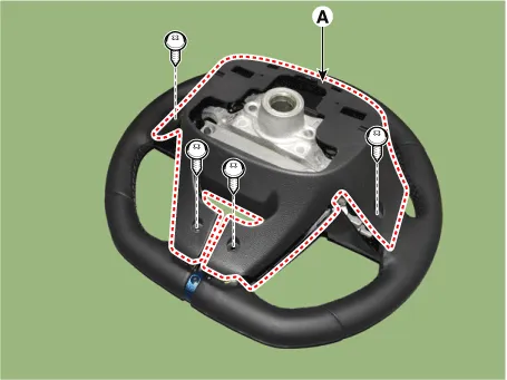
| 2. | Remove the steering wheel assembly. (Refer to Steering System -"Steering Wheel") |
| 3. | Remove the steering back cover (A).
|
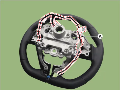
| 4. | Remove the steering remote control connector (A).
|
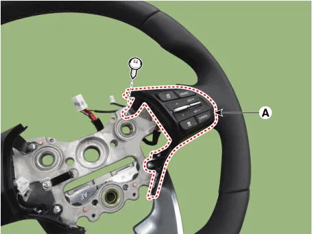
| 5. | Remove the steering remote control (A), after loosening the screws.
|
| Installation |
| 1. | Install the steering wheel remote control after connecting the connector. |
| 2. | Connect the negative (-) battery terminal. |
| Inspection |
| 1. | Remove the cruise control switch.
|
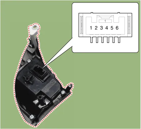
| 2. | Measure resistance between terminals on the control switch when each function switch is ON. (switch is depressed).
|
| 3. | If not within specification, replace switch. |
Circuit Diagram[Curise + SCC]
Other information:
Hyundai Ioniq (AE) 2017-2022 Service & Repair Manual: General safety information and caution
General Safety Information and CautionBe careful of the following precautions when driving the vehicle using the smart cruise control system. • The smart cruise control system may have limits in detecting distance to the vehicle ahead due to road and traffic conditions.
Hyundai Ioniq (AE) 2017-2022 Service & Repair Manual: Troubleshooting
Trouble Symptom ChartsTrouble Symptom 1Trouble Symptom 2 Trouble symptom Probable cause Remedy The set vehicle speed varies greatly upward or downward"Surging" (repeated alternating acceleration and deceleration) occurs after settingMalfunction of the vehicle speed se
Categories
- Manuals Home
- Hyundai Ioniq Owners Manual
- Hyundai Ioniq Service Manual
- Repair procedures
- Jump Starting
- Jump starting procedure
- New on site
- Most important about car

Copyright © 2026 www.hioniqae.com - 0.0144