Hyundai Ioniq (AE): Front Radar System / Smart Cruise Control (SCC) Switch. Schematic diagrams
Hyundai Ioniq (AE) 2017-2022 Service & Repair Manual / Advanced Driver Assistance System (ADAS) / Front Radar System / Smart Cruise Control (SCC) Switch. Schematic diagrams
| Circuit Diagram |
[Curise + SCC]
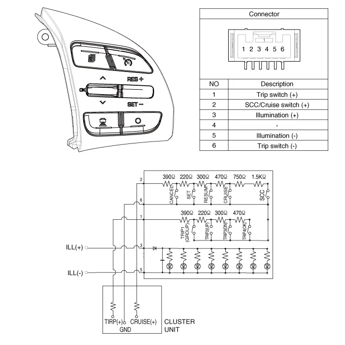
Components1. SET - switch2. RES + switch3. Distance setting switch4. CANCEL switch5. CRUISE switch
Removal1.Disconnect the negative (-) battery terminal.2.Remove the steering wheel assembly.(Refer to Steering System -"Steering Wheel")3.Remove the steering back cover (A).
Other information:
Hyundai Ioniq (AE) 2017-2022 Service & Repair Manual: Mode Control Actuator. Specifications
S
Hyundai Ioniq (AE) 2017-2022 Service & Repair Manual: Description and operation
DescriptionRear view monitor (RVM) will activate when the backup light is ON with the ignition switch ON and the shift lever in the R position.This system is a supplemental system that shows behind the vehicle through the AV monitor while backing-up. • This system is a supplementary function only.
Categories
- Manuals Home
- Hyundai Ioniq Owners Manual
- Hyundai Ioniq Service Manual
- Hybrid Control System
- Hybrid Vehicle Engine Compartment
- Heating, Ventilation and Air Conditioning
- New on site
- Most important about car

Copyright © 2026 www.hioniqae.com - 0.0136