Hyundai Ioniq (AE): DCT(Dual Clutch Transmission) System / Special service tools
| Special Service Tools |
|
Tool (Number and Name)
|
Illustration
|
Use
|
| 09200-3N000 Engine support fixture (Beam) |
| Removal and installation of the transaxle. Use this beam (SST No. : 09200-3N000) with the supporter (SST No. : 09200-2S000). ※Permit operating with 09200-38001. ※Refer to the engine support fixture assembly drawing below. |
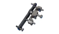
| A : 09200-2S000 B : 09200-2S100 C : 09200-2S200 Engine support fixture (Supporter) |
| Removal and installation of the transaxle. Use this beam (SST No. : 09200-38001/3N000) with the supporter (SST No. : 09200-2S000). ※Refer to the engine support fixture assembly drawing below. |
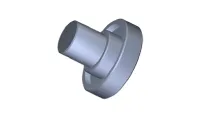
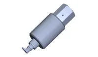
| 09430-C1190 Oil seal installer |
| Used for installing differential oil seal of both side Used with the handle (09231-H1100) |
| 09231-H1100 Handle |
| Used with the oil seal installer when installing oil seal |
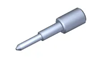
| 09480-A3800 Inhibitor switch neutral fixed pin |
| When installing the manual control lever on the inhibitor switch, used to align the neutral position. |
| 09430-C1180 Dual clutch remover |
| Used for removing dual clutch assembly |
| 09430-2A240 Dual clutch Installer |
| Used for installing dual clutch assembly |
| 09430-G2100 Clutch actuator remover |
| Used for removing clutch actuator assembly |
| 09430-F0100 Actuator fixing jig & Motor shaft reset tool |
| Used for adjusting clutch actuator Used with the Clutch actuator adjuster (09430-C1300) |
| 09430-C1300 Clutch abrasion compensation tool |
| Used for adjusting clutch actuator Used with the Clutch actuator adjustment jig (09430-F0100) |
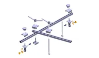


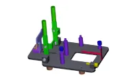
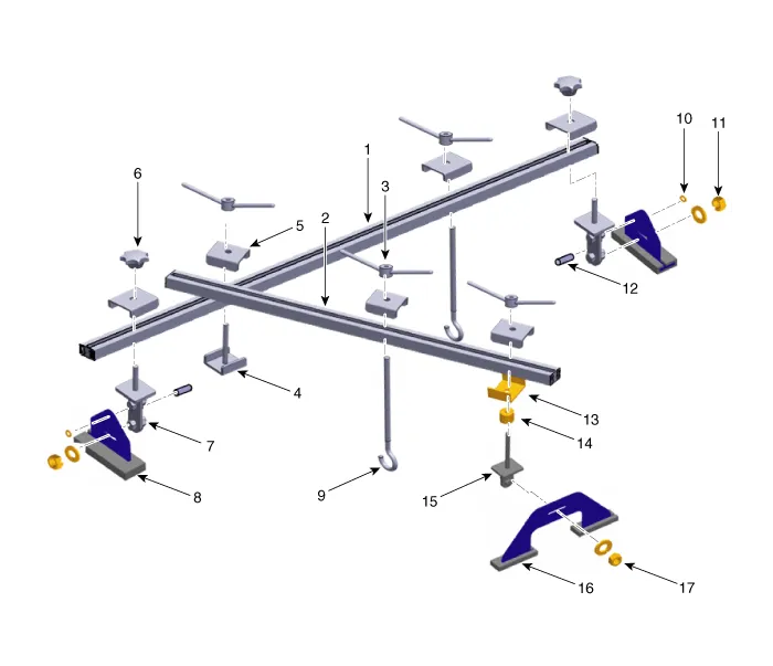
| 1. 09200-3N000(Main bar) 2. 09200-3N000(Sub bar) 3. 09200-3N000(Handle) 4. 09200-3N000(Stopper) 5. 09200-3N000(Stopper) 6. 09200-3N000(Knobe) 7. 09200-3N000(Adaptor) 8. 09200-2S000(Supporter) 9. 09200-3N000(Hanger) | 10. 09200-3N000(Clip) 11. 09200-3N000(Nut) 12. 09200-3N000(Pin) 13. 09200-2S000(Stopper) 14. 09200-2S000(Spacer) 15. 09200-2S000(Adaptor) 16. 09200-2S000(Supporter) 17. 09200-2S000(Nut) |
Specifications Transmission type D6KF1 Engine TypeKappa 1.6 GDITransmssion fluidQuantity1.6 - 1.7 L(0.
Troubleshooting Trouble symptom Probable cause Remedy Displayed the warning lamp "E"(Driving is only possible with 1/ R gear)Not performed DCT learningPerform the DCT manual learning procedure.
Other information:
Hyundai Ioniq (AE) 2017-2022 Service & Repair Manual: Photo Sensor. Description and operation
Description The photo sensor is located at the center of the defrost nozzles.The photo sensor contains a photovoltaic (sensitive to sunlight) diode. The solar radiation received by its light receiving portion, generates an electromotive force in proportion to the amount of radiation received which is transferred to the automatic temperature control
Hyundai Ioniq (AE) 2017-2022 Service & Repair Manual: Auto Defoging Actuator. Description and operation
DescriptionThe auto defogging sensor is installed on front window glass. The sensor judges and sends signal if moisture occurs to blow out wind for defogging. The air conditioner control module receives a signal from the sensor and restrains moisture and eliminates defog by the intake actuator, A/C, auto defogging actuator, blower motor rpm and mod
Categories
- Manuals Home
- Hyundai Ioniq Owners Manual
- Hyundai Ioniq Service Manual
- Driving your vehicle
- Immobilizer System
- Brake System
- New on site
- Most important about car
