Hyundai Ioniq (AE): Engine Control/Fuel System / Specifications
Fuel Delivery System
Items
|
Specification
|
Fuel Tank
| Capacity
| 45â„“ lit. (11.8 U.S.gal., 47.5 U.S.qt., 39.5 Imp.qt.)
|
Fuel Filter
| Type
| Paper type
|
Fuel Pressure
| Low Pressure Fuel Line
| 480 - 519 kPa (4.9 - 5.3 kgf/cm², 69.6 - 75.3 psi)
|
High Pressure Fuel Line
| 2 - 19.9 MPa (20.4 - 203.9 kgf/cm², 290.1 - 2900.1 psi)
|
Fuel Pump
| Type
| Electrical, in-tank type
|
Driven by
| Electric motor
|
High Pressure Fuel Pump
| Type
| Mechanical type
|
Driven by
| Camshaft
|
| •
| The fuel filter and fuel pressure regulator are embedded in the fuel pump. |
|
Sensors
| Manifold Absolute Pressure Sensor (MAPS) |
â–· Type : Piezo-resistive pressure sensor type
â–· Specification
Pressure
[kPa (kgf/cm², psi)]
|
Output Voltage (V)
|
20.0 (0.20, 2.9)
| 0.79
|
46.7 (0.47, 6.77)
| 1.84
|
101.3 (1.03, 14.7)
| 4
|
| Intake Air Temperature Sensor (IATS) |
â–· Type : Thermistor type
â–· Specification
Temperature
|
Resistance (kΩ)
|
°C
|
°F
|
-40
| -40
| 40.93 - 48.35
|
-20
| -4
| 13.89 - 16.03
|
0
| 32
| 5.38 - 6.09
|
10
| 50
| 3.48 - 3.90
|
20
| 68
| 2.31 - 2.57
|
40
| 104
| 1.08 - 1.21
|
50
| 122
| 0.76 - 0.85
|
60
| 140
| 0.54 - 0.62
|
80
| 176
| 0.29 - 0.34
|
| Mass Air Flow Sensor (MAFS) |
â–· Type : Hot-Film Type
â–· Specification
Air Flow (kg/h)
|
Frequency (kHz)
|
-40
| 1.49
|
-20
| 1.59
|
-10
| 1.68
|
-8
| 1.7
|
-6
| 1.72
|
0
| 1.81
|
6
| 1.93
|
8
| 1.97
|
10
| 2.01
|
20
| 2.21
|
40
| 2.52
|
60
| 2.74
|
90
| 3.05
|
120
| 3.34
|
140
| 3.53
|
160
| 3.73
|
250
| 4.62
|
310
| 5.28
|
370
| 6.03
|
440
| 7.06
|
560
| 9.46
|
640
| 11.83
|
| Engine Coolant Temperature Sensor (ECTS) |
â–· Type : Thermistor type
â–· Specification
Temperature
|
Resistance (kΩ)
|
°C
|
°F
|
-40
| -40
| 48.14
|
-20
| -4
| 14.13 - 16.83
|
0
| 32
| 5.79
|
20
| 68
| 2.31 - 2.59
|
40
| 104
| 1.15
|
60
| 140
| 0.59
|
80
| 176
| 0.32
|
| Exhaust Gas Temperature Sensor (EGTS) #1 |
â–· Type : Thermistor type
Temperature [°C (°F)]
|
Resistance (kΩ)
|
-40 (-40)
| 0.17
|
0 (-32)
| 0.201
|
100 (212)
| 0.276
|
200 (392)
| 0.35
|
300 (572)
| 0.42
|
400 (752)
| 0.488
|
500 (932)
| 0.554
|
600 (1112)
| 0.618
|
700 (1292)
| 0.68
|
800 (1472)
| 0.739
|
850 (1562)
| 0.767
|
| Exhaust Gas Temperature Sensor (EGTS) #2 |
â–· Type : Thermistor type
Temperature [°C (°F)]
|
Resistance (kΩ)
|
-40 (-40)
| 0.17
|
0 (-32)
| 0.201
|
100 (212)
| 0.276
|
200 (392)
| 0.35
|
300 (572)
| 0.42
|
400 (752)
| 0.488
|
500 (932)
| 0.554
|
600 (1112)
| 0.618
|
700 (1292)
| 0.68
|
800 (1472)
| 0.739
|
850 (1562)
| 0.767
|
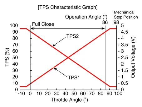
| Throttle Position Sensor (TPS) [integrated into ETC module] |
â–· Type : Hall IC Non-contact sensor type
â–· Specification
Throttle angle (°)
|
Output Voltage (V)
[Vref=5V]
|
TPS1
|
TPS2
|
0
| 0.5
| 4.5
|
10
| 0.96
| 4.05
|
20
| 1.41
| 3.59
|
30
| 1.87
| 3.14
|
40
| 2.32
| 2.68
|
50
| 2.78
| 2.23
|
60
| 3.23
| 1.77
|
70
| 3.69
| 1.32
|
80
| 4.14
| 0.86
|
90
| 4.60
| 0.41
|
98
| 4.65
| 0.35
|
C.T (0)
| 0.5
| 4.50
|
W.O.T (86)
| 4.41
| 0.59
|
| Crankshaft Position Sensor (CKPS) |
â–· Type : Magnetic field sensitive Type
â–· Specification
Item
|
Specification
|
Coil Resistance (Ω)
| 774 - 946 [20°C (68°F)]
|
| Camshaft Position Sensor (CMPS) |
â–· Type : Hall effect type
â–· Type : Piezo-electricity type
â–· Specification
Item
|
Specification
|
Capacitance (pF)
| 850 - 1,150
|
Coil Resistance (MΩ)
| 1
|
| Heated Oxygen Sensor (HO2S) [Bank 1/Sensor 1] |
â–· Type : Zirconia (ZrO2) [Linear] type
â–· Specification
Item
|
Specification
|
Heater Resistance (Ω)
| 2.4 - 4.0 [20°C (68°F)]
|
| Heated Oxygen Sensor (HO2S) [Bank 1/Sensor 2] |
â–· Type : Zirconia (ZrO2) [Binary] type
â–· Specification
A/F Ratio (λ)
|
Output Voltage (V)
|
RICH
| 0.6 - 1.0
|
LEAN
| 0 - 0.4
|
Item
|
Specification
|
Heater Resistance (Ω)
| Approx. 9.0 [20°C (68°F)]
|
| Rail Pressure Sensor (RPS) |
â–· Type : Piezo-electricity type
â–· Specification

| Accelerator Position Sensor (APS) |
â–· Type : Variable resistor type
â–· Specification
Accelerator Position
|
Output Voltage (V)
|
APS1
|
APS2
|
C.T
| 0.7 - 0.8
| 0.325 - 0.425
|
W.O.T
| 3.98 - 4.22
| 1.98 - 2.13
|
Actuators
â–· Specification
Item
|
Specification
|
Coil Resistance (Ω)
| 1.425 - 1.575 [20°C (68°F)]
|
| ETC Motor [integrated into ETC Module] |
â–· Specification
Item
|
Specification
|
Coil Resistance (Ω)
| 0.3 - 100 [20°C (68°F)]
|
| Purge Control Solenoid Valve (PCSV) |
â–· Specification
Item
|
Specification
|
Coil Resistance (Ω)
| 22.0 - 26.0 [20°C (68°F)]
|
| CVVT Oil Control Solenoid (OCS) [Intake] |
â–· Specification
Item
|
Specification
|
Coil Resistance (Ω)
| 5.8 - 6.8 [20°C (68°F)]
|
| CVVT Oil Control Valve (OCV) [Exhaust] |
â–· Specification
Item
|
Specification
|
Coil Resistance (Ω)
| 6.9 - 7.9 [20°C (68°F)]
|
â–· Type : Stick type
â–· Specification
Item
|
Specification
|
Coil Resistance (Ω)
| 0.56 ± 10% [20°C (68°F)]
|
| Fuel Pressure Control Valve |
â–· Specification
Item
|
Specification
|
Coil Resistance (Ω)
| 0.49 ± 5% [20°C (68°F)]
|
Item
|
Specification
|
Ignition Timing (°)
| BTDC 0 ± 10
|
Idle Speed (rpm)
| A/C OFF
| Neutral, N, P-range
| 630 ± 100
|
D-range
| 630 ± 100
|
A/C ON
| Neutral, N, P-range
| 700 ± 100
|
D, R-range
| 680 ± 100
|
Engine Control System
Item
|
kgf.m
|
N.m
|
lb-ft
|
ECM installation bolt
| 1.0 - 1.2
| 9.8 - 11.8
| 7.2 - 8.7
|
ECM bracket installation bolt/nut
| 1.0 - 1.2
| 9.8 - 11.8
| 7.2 - 8.7
|
Mass air flow sensor clamp installation bolts
| 0.3 - 0.5
| 2.9 - 4.9
| 2.2 - 3.6
|
Mass air flow sensor installation bolts
| 0.3 - 0.5
| 2.9 - 4.9
| 2.2 - 3.6
|
Manifold absolute pressure sensor installation bolt
| 1.0 - 1.2
| 9.8 - 11.8
| 7.2 - 8.7
|
Engine Coolant Temperature Sensor installation
| 3.0 - 4.0
| 29.4 - 39.2
| 21.7 - 28.9
|
Crankshaft position sensor installation bolt
| 1.0 - 1.2
| 9.8 - 11.8
| 7.2 - 8.7
|
Camshaft position sensor (Bank 1 / Intake) installation bolt
| 0.8 - 1.2
| 7.8 - 11.8
| 5.8 - 8.7
|
Camshaft position sensor (Bank 1 / Exhaust) installation bolt
| 0.8 - 1.2
| 7.8 - 11.8
| 5.8 - 8.7
|
Knock sensor installation bolt
| 1.9 - 2.4
| 18.6 - 23.5
| 13.7 - 17.4
|
Heated oxygen sensor (Bank 1 / sensor 1) installation
| 4.0 - 5.0
| 39.2 - 49.1
| 28.9 - 36.2
|
Heated oxygen sensor (Bank 1 / sensor 2) installation
| 4.0 - 5.0
| 39.2 - 49.1
| 28.9 - 36.2
|
Rail pressure sensor installation
| 3.0 - 3.5
| 30.0 - 34.3
| 22.1 - 25.3
|
Electronic throttle body installation bolt
| 0.8 - 1.0
| 7.8 - 9.8
| 5.8 - 7.2
|
Purge Control Solenoid Valve barcket installation bolt
| 1.0 - 1.2
| 9.8 - 11.8
| 7.2 - 8.7
|
CVVT oil control solenoid (Bank 1 / Intake) installation bolt
| 1.0 - 1.2
| 9.8 - 11.8
| 7.2 - 8.7
|
CVVT oil control valve (Bank 1 / Exhaust) installation bolt
| 1.0 - 1.2
| 9.8 - 11.8
| 7.2 - 8.7
|
Ignition coil installation bolt
| 1.0 - 1.2
| 9.8 - 11.8
| 7.2 - 8.7
|
Fuel Delivery System
Item
|
kgf.m
|
N.m
|
lb-ft
|
Fuel tank installation nut
| 4.0 - 5.5
| 39.2 - 54.0
| 28.9 - 39.8
|
Filler-neck assembly bracket installation nut
| 0.8 - 1.2
| 7.8 - 11.8
| 5.8 - 8.7
|
Filler-neck assembly bracket installation screw
| 0.8 - 1.2
| 7.8 - 11.8
| 5.8 - 8.7
|
Accelerator pedal module installation nut
| 1.3 - 1.6
| 12.8 - 15.7
| 9.4 - 11.6
|
Accelerator pedal module installation bolt
| 0.9 - 1.4
| 8.8 - 13.7
| 6.5 - 10.1
|
Delivery pipe installation bolt
| 1.9 - 2.4
| 18.6 - 23.5
| 13.7 - 17.4
|
High pressure fuel pump function bolck installation bolt
| 1.0 - 1.2
| 9.8 - 11.8
| 7.2 - 8.7
|
High pressure fuel pump installation bolt
| 1.3 - 1.5
| 12.8 - 14.7
| 9.4 - 10.9
|
High pressure fuel pipe installation nut
| 2.7 - 3.3
| 26.5 - 32.4
| 19.5 - 23.9
|
High Voltage Shut-off Procedures
•
Be sure to read and follow the "General Safety Information and Caution" before doing any work related with the high voltage system.
Special Service Tools
Item
Illustration
Application
Fuel Pressure Gauge(09353-24100)Measuring the fuel line pressureFuel Pressure Gauge Adapter(09353-02100)Connection between the high pressure fuel pump and the fuel feed lineHeated Oxygen Sensor Socket Wrench(09392-1Y100)Removal and installation of the heated oxygen sensor※ SST No.
Other information:
Inspection
•
Before measuring the pressure of the refriferant line, check whether the refrigerant amount is charged in accordance with the specified charging amount.(Refer to Heating, Ventilation, Air Conditioning - "Specifications")1.
System Block DiagramComponent Parts and Function Outline
Component part
Function
Vehicle-speed sensor, ESP/ABS Control ModuleConverts vehicle speed to pulse.VCUReceives signals from sensor and control switches.

