Hyundai Ioniq (AE): Brake System / Stop Lamp Switch. Schematic diagrams
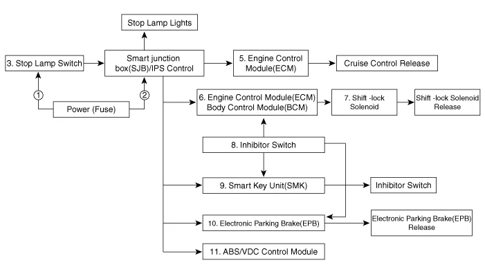
| Schematic Diagram |
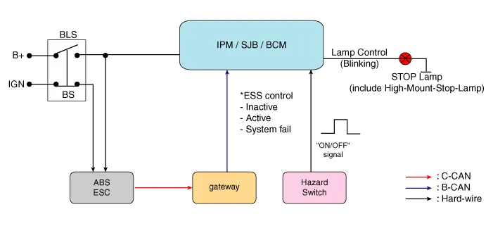
| System Circuit Diagram |
| Terminal Function |

|
Teminal
|
Description
|
| 1 | IGN1 |
| 2 | Engine Control Module (ECM) |
| 3 | B+ |
| 4 | Stop Lamp |
Components Location1. Brake pedal member assembly2. Stop lamp switch3. Brake pedal arm assembly4. Brake pedal pad5. Pedal stroke sensor
Removal1.Turn ignition switch OFF and disconnect the negative (-) battery cable.2.Remove the lower crash pad.(Refer to Body - "Crash Pad")3.Remove the knee airbag.
Other information:
Hyundai Ioniq (AE) 2017-2022 Service & Repair Manual: Ambient Temperature Sensor. Repair procedures
Inspection1.Check the resistance of the ambient temperature sensor between terminals 1 and 2 whether it changes by changing the ambient temperature.1. Ambient Sensor (+)2. Sensor groundSpecification Ambient temperature [°C (°F)] Resistance between terminal 1 and 2 (
Hyundai Ioniq (AE) 2017-2022 Service & Repair Manual: emperature Control Actuator. Description and operation
DescriptionThe temperature control actuator is located at the heater unit. It regulates the temperature by the procedure as follows. The signal from the control unit adjusts the position of the temperature door by operating the temperature switch. Then the temperature will be regulated by the hot/cold air ratio decided by the position of the temper
Categories
- Manuals Home
- Hyundai Ioniq Owners Manual
- Hyundai Ioniq Service Manual
- Description and operation
- Repair procedures
- If the 12 Volt Battery is Discharged (Hybrid Vehicle)
- New on site
- Most important about car
