Hyundai Ioniq: Front Suspension System / Sub Frame. Repair procedures
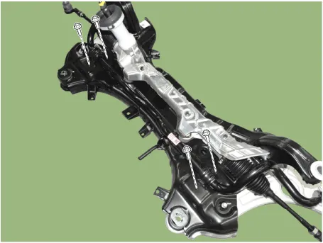
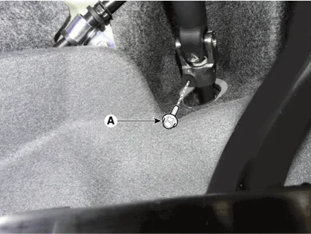
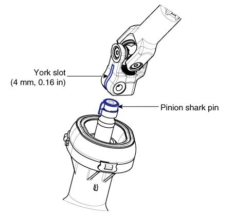
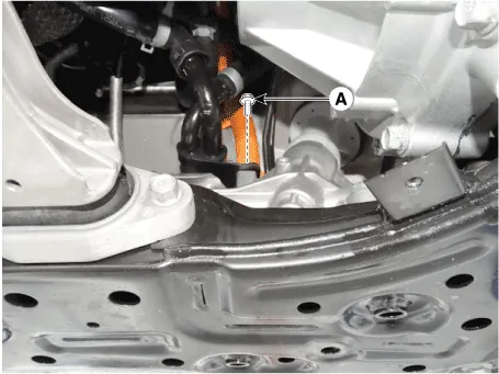
1. | Loosen the bolt (A) and then disconnect the universal joint assembly from the pinion of the steering gear box. Tightening torque : M8 BOLT : 32.4 - 37.3 N.m (3.3 - 3.8 kgf.m, 23.9 - 27.5 lb-ft) M10 BOLT : 49.0 - 58.8 N.m (5.0 - 6.0 kgf.m, 36.2 - 43.4 lb-ft) |
![](images/sub_frame_repair_procedures-898/413/saest6h030d_n.gif)
•
| Lock the steering wheel in the straight ahead position to prevent the damage of the clock spring inner cable. |
•
| When assembling, insert the shark pin into the universal joint york slot as the illustration below. ![](images/sub_frame_repair_procedures-898/413/sadst60102l_n.gif)
|
|
|
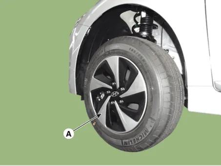
2. | Loosen the wheel nuts slightly. Raise the vehicle, and make sure it is securely supported. |
3. | Remove the front wheel and tire (A) from the front hub. Tightening torque : 107.9 - 127.5 N.m (11.0 - 13.0 kgf.m, 79.6 - 94.0 lb-ft) |
![](images/sub_frame_repair_procedures-898/413/saeds6h010d_n.gif)
•
| Be careful not to damage the hub bolts when removing the front wheel and tire. |
|
|
4. | Remove the tie rod end ball joint. (1) | Rmove the split pin (C). |
(3) | Using SST(09568-1S100), separate the ball joint (A) from the knuckle. |
Tightening torque : 78.5 - 98.1 N.m (8.0 - 10.0 kgf.m, 57.9 - 72.3 lb-ft) |
![](images/sub_frame_repair_procedures-898/413/saeds6h011d_n.gif)
![](images/sub_frame_repair_procedures-898/413/saeds6h013d_n.gif)
|
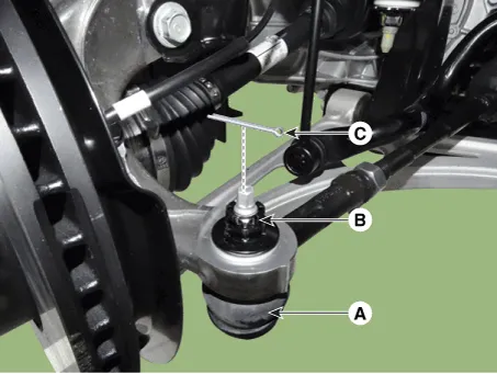
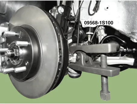
5. | Loosen the lower arm nut and then remove the lower arm ball joint by using SST(09568-1S100). (1) | Rmove the split pin (B). |
(2) | Loosen the nut (C) and washer (D). |
(3) | Using SST(09568-1S100), separate the ball joint (A) from the knuckle. Tightening torque : 78.5 - 98.1 N.m (8.0 - 10.0 kgf.m, 57.9 - 72.3 lb-ft) |
![](images/sub_frame_repair_procedures-898/413/saeds6h014d_n.gif)
![](images/sub_frame_repair_procedures-898/413/saeds6h016d_n.gif)
•
| Do not reuse the lower arm lock nut (C). |
|
|
|
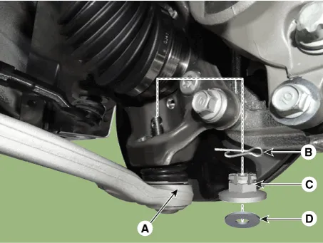
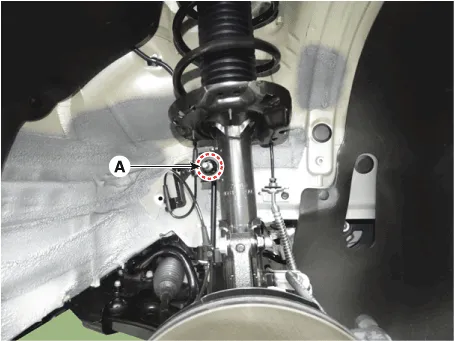
6. | Disconnect the stabilizer link with the front strut assembly after loosening the nut (A). Tightening torque : 98.1 - 117.7 N.m (10.0 - 12.0 kgf.m, 72.3 - 86.8 lb-ft) |
![](images/sub_frame_repair_procedures-898/413/sadss60004d_n.gif)
•
| When loosening the nut (A), fix the outer hexagon of stabilizer bar link. |
•
| Be careful not to damage the stabilizer link boots. |
|
|
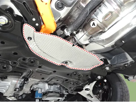
7. | Remove the heat protector (A). Tightening torque : 9.8 - 11.8 N.m (1.0 - 1.2 kgf.m, 7.2 - 8.7 lb-ft) |
![](images/sub_frame_repair_procedures-898/413/saeem6h144d_n.gif)
|
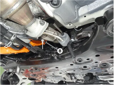
8. | Loosen the mounting bolt (A)&(B) then remove the pipe from the sub frame. ![](images/sub_frame_repair_procedures-898/413/saess6h005d_n.gif)
![](images/sub_frame_repair_procedures-898/413/saess6h006d_n.gif)
|
9. | Remove the muffler rubber hanger (A). ![](images/sub_frame_repair_procedures-898/413/saess6h007d_n.gif)
|
10. | Remove the roll rod stopper (A) by loosening the bolt and nut. Tightening torque : 107.9 - 127.5 N.m (11.0 - 13.0 kgf.m, 79.6 - 94.0 lb-ft) |
![](images/sub_frame_repair_procedures-898/413/saess6h101d_n.gif)
•
| Set up a transmission jack for safety. |
![](images/sub_frame_repair_procedures-898/413/sadss60017d_n.gif)
|
|
11. | Loosen the mounting bolts and then remove the stabilizer bar. Tightening torque : 44.1 - 53.9 N.m (4.5 - 5.5 kgf.m, 32.5 - 39.8 lb-ft) |
![](images/sub_frame_repair_procedures-898/413/saess6h009d_n.gif)
|
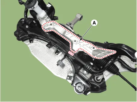
12. | Remove the protector (A). Tightening torque : 6.9 - 10.8 N.m (0.7 - 1.1 kgf.m, 5.1 - 8.0 lb-ft) |
![](images/sub_frame_repair_procedures-898/413/saest6h035d_n.gif)
|
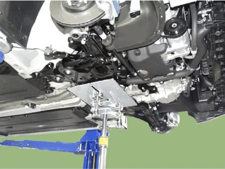
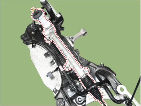
13. | Remove the steering gearbox from the front sub frame by loosening the mounting bolts. Tightening torque : 88.2 - 107.8 N.m (9.0 - 11.0 kgf.m, 65.0 - 79.5 lb-ft) |
![](images/sub_frame_repair_procedures-898/413/saest6h036d_n.gif)
|
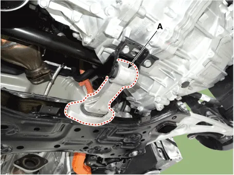
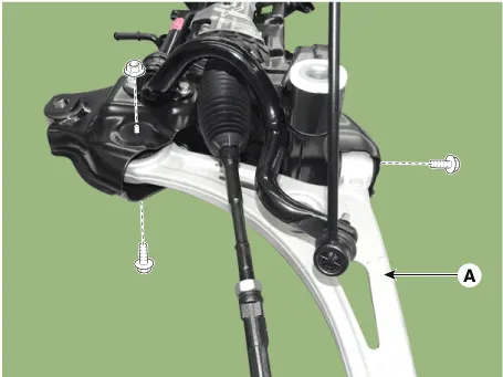
14. | Remove the front lower (A) arm after loosening the bolts & nuts. Tightening torque Front : 117.7 - 137.3 N.m (12.0 - 14.0 kgf.m, 86.8 - 101.3 lb-ft) Rear : 156.9 - 176.5 N.m (16.0 - 18.0 kgf.m, 115.7 - 130.2 lb-ft) |
![](images/sub_frame_repair_procedures-898/413/saess6h004d_n.gif)
|
15. | Install in the reverse order of removal. |
16. | Check the wheel Alignment. (Refer to Tires/Wheels - "Alignment") |
Removal1.Loosen the bolt (A) and then disconnect the universal joint assembly from the pinion of the steering gear box. Tightening torque : 32...
Other information:
Specifications
Classification
Unit
Specifications
VoltageVdc204DrivingTorqueNm / rpm / sec35.3 / 0 - 2160 / 5OutputkW / rpm / sec8.0 / 2160 - 12000 / 5GenerativeTorqueNm / rpm / Min21...
Description•
Function
The Transmission Control Module (TCM) is like the brain for the Dual Clutch Transmission (DCT). It receives information from various sensors for a wide range of transmission controls to provide an optimal driving environment for the driver...
Categories
![Hyundai Ioniq. Hybrid Vehicle Engine Compartment](images/books/1/hyundai_ioniq_hybrid_vehicle_engine_compartment_5.png)
1. Engine oil filler cap
2. Engine oil dipstick
3. Engine coolant cap
4. Engine coolant reservoir
5. Inverter coolant reservoir
read more