Hyundai Ioniq (AE): Heater / Heater Unit. Components and components location
| Component Location |
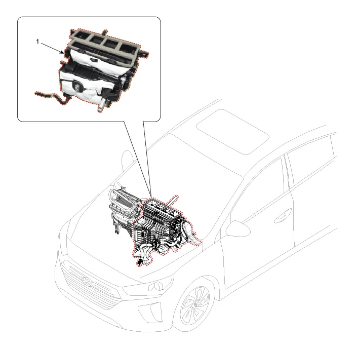
| 1. Heater unit assembly |
| Compoents |
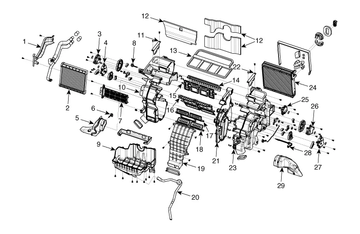
| 1. Heater core cover 2. Heater core & Seal assembly 3. Mode actuator [LH] 4. Temperature control actuator [LH] 5. Shower duct [LH] 6. Duct sensor [Floor] 7. PTC Heater 8. Duct sensor [Vent] 9. Heater & Evaporator lower case 10. Heater case [LH] | 11. Air guide [LH] 12. Heater unit pad 13. Center duct seal 14. Deforster door assembly 15. Vent door assembly 16. Floor door assembly 17. Console vent door assembly 18. Console floor door assembly 19. Vent guide 20. Drain hose | 21. Separator 22. Air guide [RH] 23. Heater case [RH] 24. Evaporator core assembly 25. Auto defogging actuator 26. Mode actuator [RH] 27. Temperature control actuator [RH] 28. Evaporator temperature sensor 29. Shower duct [RH] |
Replacement When prying with a flat-tip screwdriver or use a prying trim tool, wrap it with protective tape, and apply protective tape around the related parts, to prevent damage.
Other information:
Hyundai Ioniq (AE) 2017-2022 Service & Repair Manual: Photo Sensor. Repair procedures
Inspection1.Turn the ignition switch ON.2.Connect the GDS.3.Emit intensive light toward the photo sensor using a lamp, and check the output voltage change.4.The voltage will rise with higher intensive light and reduce with lower intensive light.1. Auto light signal2.
Hyundai Ioniq (AE) 2017-2022 Service & Repair Manual: emperature Control Actuator. Description and operation
DescriptionThe temperature control actuator is located at the heater unit. It regulates the temperature by the procedure as follows. The signal from the control unit adjusts the position of the temperature door by operating the temperature switch. Then the temperature will be regulated by the hot/cold air ratio decided by the position of the temper
Categories
- Manuals Home
- Hyundai Ioniq Owners Manual
- Hyundai Ioniq Service Manual
- DCT(Dual Clutch Transmission) System
- Transmission Gear Oil. Repair procedures
- Maintenance
- New on site
- Most important about car
