
Hyundai Ioniq (AE): Electric A/C Compressor / Troubleshooting
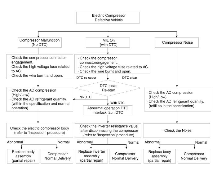
| Troubleshooting |
Connector ConfigurationsTerminal Function Connector Pin No. Function A112V Power Ground2Climate CAN Low3Interlock (-)412V Power5Climate CAN High6Interlock (+)B1High Voltage Power2High Voltage Ground3Compressor Interlock (-)4Compressor Interlock (+)
Inspection[Electric A/C Compressor body inside inspection]1.Electric compressor body inside check procedure.1)Remove the low-pressure pipe from the electric compressor.
Other information:
Hyundai Ioniq (AE) 2017-2022 Service & Repair Manual: Description and operation
DescriptionIn ordinary cars, the mechanical water pump mounted on the engine for heating purposes is activated to circulate the cooling water, but in hybrid cars, AEWP is used to circulate the cooling water when the engine is not operating. Classification System Cooling water used
Hyundai Ioniq (AE) 2017-2022 Service & Repair Manual: Description and operation
DescriptionRear corner radar is a system that uses two magnetic wave radar sensors attached on the rear panel to measure the distance from the following vehicles and provides the sensing and (visual and auditory) alarm of any vehicle coming into the blind spot.
Categories
- Manuals Home
- Hyundai Ioniq Owners Manual
- Hyundai Ioniq Service Manual
- Body (Interior and Exterior)
- Maintenance
- Repair procedures
- New on site
- Most important about car
