
Hyundai Ioniq (AE): Audio / Audio Unit. Components and components location
Hyundai Ioniq (AE) 2017-2022 Service & Repair Manual / Body Electrical System / Audio / Audio Unit. Components and components location
| Components |
[RADIO/CD/MP3]
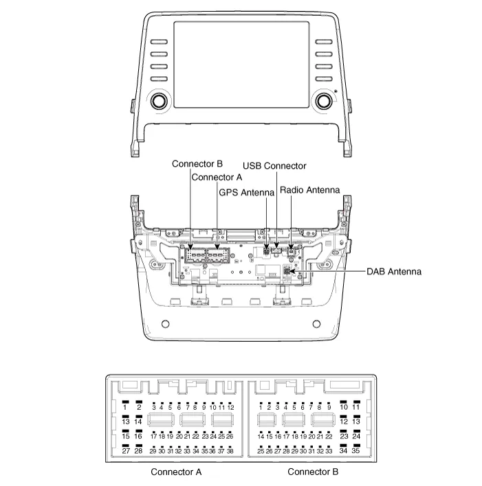
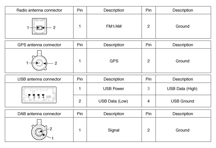
Connector Pin Information
|
No
|
Connector A
|
Connector B
|
| 1 | Rear speaker (LH +) | - |
| 2 | Rear speaker (LH -) | Mic (+) |
| 3 | - | - |
| 4 | - | - |
| 5 | - | Antenna power |
| 6 | Camera power | Illumination (+) |
| 7 | Camera vidio input | MM CAN (+) |
| 8 | - | - |
| 9 | - | - |
| 10 | - | Battery (+) |
| 11 | DTC | Battery (+) |
| 12 | Steering key signal | Ground |
| 13 | Front speaker (LH +) | Ground |
| 14 | Front speaker (LH -) | - |
| 15 | Front speaker (RH -) | Mic (-) |
| 16 | Front speaker (RH +) | - |
| 17 | - | - |
| 18 | - | - |
| 19 | - | Illumination (-) |
| 20 | Camera power ground | MM CAN (-) |
| 21 | Camera video ground | - |
| 22 | - | ACC |
| 23 | - | - |
| 24 | - | - |
| 25 | - | - |
| 26 | Steering key ground | - |
| 27 | Rear speaker (RH -) | - |
| 28 | Rear speaker (RH +) | - |
| 29 | - | - |
| 30 | - | - |
| 31 | - | IGN 3 |
| 32 | Camera(NC.) /NON Camera(GND) | IGN 1 |
| 33 | Camera shield ground | - |
| 34 | - | - |
| 35 | - | - |
| 36 | - | |
| 37 | - | |
| 38 | Speed |
Component Location1. Audio unit2. Antenna feeder cable connector3. Roof antenna (Audio)4. Front door speaker5. Rear door speaker6. Antenna feeder cable7.
Removal1.Disconnect the negative (-) battery terminal.2.Remove the cluster fascia panal.(Refer to Body - "Center Fascia Panal")3.Remove the crash pad garnish RH.
Other information:
Hyundai Ioniq (AE) 2017-2022 Service & Repair Manual: Ambient Temperature Sensor. Description and operation
DescriptionThe ambient temperature sensor is located at the front of the condenser and detects ambient air temperature. It is a negative type thermistor; resistance will increase with lower temperature, and decrease with higher temperature.The sensor output will be used for discharge temperature control, temperature regulation door contrl, blower m
Hyundai Ioniq (AE) 2017-2022 Service & Repair Manual: Warning Indicator. Components and components location
C
Categories
- Manuals Home
- Hyundai Ioniq Owners Manual
- Hyundai Ioniq Service Manual
- Troubleshooting
- Jump starting procedure
- Description and operation
- New on site
- Most important about car

Copyright В© 2026 www.hioniqae.com - 0.0237