Hyundai Ioniq (AE): High Voltage Battery Control System / Battery Temperature Sensor. Specifications
| Specification |
|
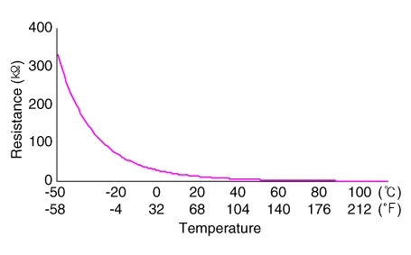
Temperature
|
Resistance (kΩ)
| |
|
°C
|
°F
| |
| -50 | -58 | 314.9 - 344.6 |
| -40 | -40 | 181.1 - 196.0 |
| -30 | -22 | 107.5 - 115.2 |
| -20 | -4 | 65.82 - 69.77 |
| -10 | 14 | 41.43 - 43.52 |
| 0 | 32 | 26.74 - 27.83 |
| 10 | 50 | 17.67 - 18.25 |
| 20 | 68 | 11.94 - 12.24 |
| 30 | 86 | 8.214 - 8.411 |
| 40 | 104 | 5.738 - 5.918 |
| 50 | 122 | 4.082 - 4.239 |
| 60 | 140 | 2.954 - 3.087 |
| 70 | 158 | 2.172 - 2.284 |
| 80 | 176 | 1.621 - 1.715 |
| 90 | 194 | 1.227 - 1.305 |
| 100 | 212 | 0.941 - 1.006 |
| 110 | 230 | 0.731 - 0.785 |
|
Temperature
|
Resistance (kΩ)
| |
|
°C
|
°F
| |
| -50 | -58 | 351.1 - 385.0 |
| -40 | -40 | 196.6 - 213.1 |
| -30 | -22 | 114.4 - 122.7 |
| -20 | -4 | 68.94 - 73.15 |
| -10 | 14 | 42.59 - 44.76 |
| 0 | 32 | 27.14 - 28.27 |
| 10 | 50 | 17.78 - 18.36 |
| 20 | 68 | 11.96 - 12.25 |
| 30 | 86 | 8.202 - 8.399 |
| 40 | 104 | 5.721 - 5.901 |
| 50 | 122 | 4.069 - 4.226 |
| 60 | 140 | 2.945 - 3.078 |
| 70 | 158 | 2.169 - 2.280 |
| 80 | 176 | 1.622 - 1.715 |
| 90 | 194 | 1.228 - 1.306 |
DescriptionBattery Temperature Sensor is installed inside the high voltage battery pack assembly. It measures the temperature of the battery module 1, 4 and air inlet.
Circuit Diagram
Other information:
Hyundai Ioniq (AE) 2017-2022 Service & Repair Manual: General safety information and caution
Safety PrecautionPrecautions To Take Before Servicing High Voltage System • Since hybrid vehicles contain a high voltage battery, if the high voltage system or vehicles are handled incorrectly, this might lead to a serious accidents like electric shock and electric leakage.
Hyundai Ioniq (AE) 2017-2022 Service & Repair Manual: Description and operation
DescriptionRear corner radar is a system that uses two magnetic wave radar sensors attached on the rear panel to measure the distance from the following vehicles and provides the sensing and (visual and auditory) alarm of any vehicle coming into the blind spot.
Categories
- Manuals Home
- Hyundai Ioniq Owners Manual
- Hyundai Ioniq Service Manual
- Heating, Ventilation and Air Conditioning
- Jump starting procedure
- Suspension System
- New on site
- Most important about car
