Hyundai Ioniq (AE): Engine Control System / Camshaft Position Sensor (CMPS). Repair procedures
| Inspection |
| 1. | Check the signal waveform of the CMPS and CKPS using the GDS.
|
| Removal |
|

| 1. | Turn the ignition switch OFF and disconnect the battery negative (-) cable. |
| 2. | Remove the air cleaner assembly (Refer to Engine Mechanical System - "Air Cleaner") |
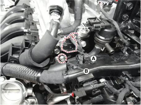
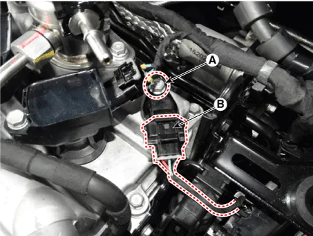
| 3. | Disconnect the camshaft position sensor connector (A). |
| 4. | Remove the installation bolt (B), and then remove the sensor.
|
| 1. | Turn the ignition switch OFF and disconnect the battery negative (-) cable. |
| 2. | Remove the air cleaner assembly (Refer to Engine Mechanical System - "Air Cleaner") |
| 3. | Disconnect the camshaft position sensor connector (A). |
| 4. | Remove the installation bolt (B), and then remove the sensor.
|
| Installation |
|

|
|
|
| 1. | Install in the reverse order of removal.
|
Circuit Diagram
DescriptionKnocking is a phenomenon characterized by undesirable vibration and noise and can cause engine damage. Knock Sensor (KS) is installed on the cylinder block and senses engine knocking.
Other information:
Hyundai Ioniq (AE) 2017-2022 Service & Repair Manual: Front Radar Unit. Description and operation
DescriptionThe smart cruise control unit is installed on the front right side of the chassis. A radar sensor is embedded in the front section of the unit. This sensor detects vehicles and objects in front of the vehicle. The radar sensor can detect up to 64 objects ahead of a vehicle.
Hyundai Ioniq (AE) 2017-2022 Service & Repair Manual: Schematic diagrams
System Block DiagramComponent Parts and Function Outline Component part Function Vehicle-speed sensor, ESP/ABS Control ModuleConverts vehicle speed to pulse.VCUReceives signals from sensor and control switches.
Categories
- Manuals Home
- Hyundai Ioniq Owners Manual
- Hyundai Ioniq Service Manual
- Jump starting procedure
- Jump Starting
- Heating, Ventilation and Air Conditioning
- New on site
- Most important about car
