Hyundai Ioniq (AE): Clutch System / Clutch Cover And Disc. Repair procedures
Hyundai Ioniq (AE) 2017-2022 Service & Repair Manual / Engine Clutch System / Clutch System / Clutch Cover And Disc. Repair procedures
| Removal |
| 1. | Remove the hybrid motor assembly. (Refer to Hybrid Motor System - "Hybrid Motor Assembly") |
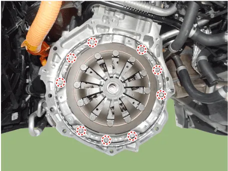
| 2. | Remove the clutch cover assembly and clutch disc after loosening the bolts.
|

| Inspection |
| 1. | Inspect diaphragm spring wear which is in contact with a concentric slave cylinder bearing. |
| 2. | Check the clutch cover and disc surface for wear or cracks. |
| 3. | Check the clutch disc lining for slipping or oil marks. |
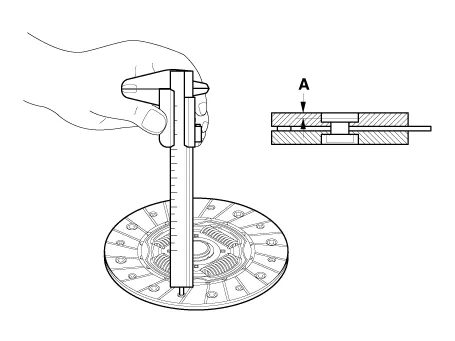
| 4. | Measure the depth from a clutch lining surface to a rivet. If the measured value is less than the specification below, replace it.
|
| Installation |
|
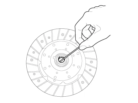
| 1. | Apply grease on a disc spline part and hybrid motor input shaft spline part as required.
|
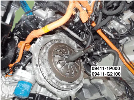
| 2. | Install the clutch disc and the cover with SST (09411-1P000, 09411-G2100)
|
| 3. | Install the clutch cover bolts. Not to be bent or twisted, Tighten them in diagonal directions.
|
| 4. | Install the hybrid motor assembly. (Refer to Hybrid Motor System - "Hybrid Motor Assembly") |
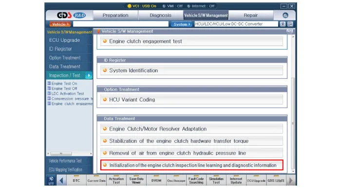
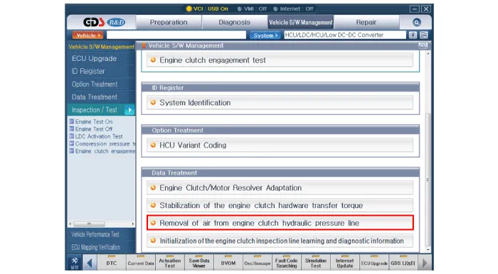
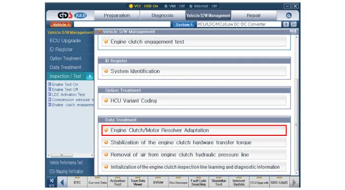
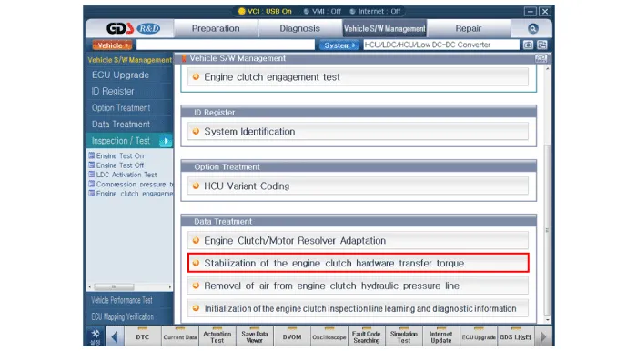
| 5. | After replacing the Engine clutch actuator, operate the followings in order using GDS equipment.
|

Components 1. Clutch disc2. Clutch cover3. Concentric slave cylinder4. Hybrid motor assembly5. Engine clutch actuator6. Reservoir
Components 1. Clutch disc2. Clutch cover3. Concentric slave cylinder4. Hybrid motor assembly5. Engine clutch actuator6. Reservoir
Other information:
Hyundai Ioniq (AE) 2017-2022 Service & Repair Manual: Front Radar Unit. Specifications
S
Hyundai Ioniq (AE) 2017-2022 Service & Repair Manual: Description and operation
DescriptionRear view monitor (RVM) will activate when the backup light is ON with the ignition switch ON and the shift lever in the R position.This system is a supplemental system that shows behind the vehicle through the AV monitor while backing-up. • This system is a supplementary function only.
Categories
- Manuals Home
- Hyundai Ioniq Owners Manual
- Hyundai Ioniq Service Manual
- Body (Interior and Exterior)
- Heating, Ventilation and Air Conditioning
- Jump Starting
- New on site
- Most important about car

Copyright © 2026 www.hioniqae.com - 0.0166