Hyundai Ioniq (AE): Emergency Call System / Emergency Call (eCall) Antenna. Repair procedures
Hyundai Ioniq (AE) 2017-2022 Service & Repair Manual / Body Electrical System / Emergency Call System / Emergency Call (eCall) Antenna. Repair procedures
| Removal |
| 1. | Disconnect the negative (-) battery terminal. |
| 2. | Remove the roof trim assembly. (Refer to Body - "Roof Trim Assembly") |
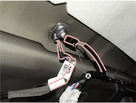
| 3. | Disconnect the roof antenna cable and connectors (A).
|
| 4. | Remove the roof antenna after loosening a nut (A).
|

| Installation |
|

| 1. | Install the antenna and then connect the roof antenna connectors. |
| 2. | Install the roof trim assembly. |
ComponentsRADIO+GNSS+eCallRADIO+GNSS+DAB+eCall
REMOVAL1.Disconnect the negative (-) battery terminal.2.Remove the glove box upper cover assembly.(Refer to Body - "Glove Box Upper Cover Assembly")3.Remove the E-call speaker (A) by loosening the nuts after disconnecting the connector (B).
Other information:
Hyundai Ioniq (AE) 2017-2022 Service & Repair Manual: Rear Corner Safety ON/OFF Switch. Repair procedures
Inspection1.Disconnect the negative (-) battery terminal.2.Remove the crash pad lower panel.(Refer to Body - "Crash Pad Lower Panel")3.Remove the lower crash pad switch assembly (A) after disengaging the mounting clip.4.Remove the rheostat switch connector (A).
Hyundai Ioniq (AE) 2017-2022 Service & Repair Manual: Warning Indicator. Components and components location
C
Categories
- Manuals Home
- Hyundai Ioniq Owners Manual
- Hyundai Ioniq Service Manual
- Jump starting procedure
- Hybrid Vehicle Engine Compartment
- Jump Starting
- New on site
- Most important about car

Copyright © 2026 www.hioniqae.com - 0.0182