Hyundai Ioniq (AE): Engine Control System / Engine Coolant Temperature Sensor (ECTS). Repair procedures
| 1. | Turn the ignition switch OFF. |
| 2. | Remove the ECTS. (Refer to "Removal") |
| 3. | After immersing the thermistor of the sensor into engine coolant, measure resistance between the ECTS terminals 1 and 3. |
| 4. | Check that the resistance is within the specification. Specification : Refer to "Specification" |
|
Engine Coolant Temperature Sensor (ECTS) [Water Temperature Control Assembly]
| 1. | Turn ignition switch OFF and disconnect the negative (-) battery cable. |
| 2. | Remove the air cleaner assembly (Refer to Engine Mechanical System - "Air Cleaner") |
| 3. | Remove the purge control solenoid valve. (Refer to Engine Control System - "Purge Control Solenoid Valve (PCSV)") |
| 4. | Disconnect the engine coolant temperature sensor connector (A). |
| 5. | Remove the engine coolant temperature sensor after removing the fixing pin (B). 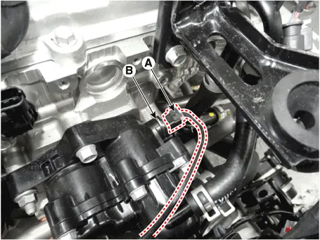
| •
| Note that engine coolant may flow out from the water temperature control assembly when removing the sensor. |
|
|
| 6. | Fill with engine coolant. (Refer to Engine Mechanical System - "Coolant") |
Engine Coolant Temperature Sensor (ECTS) [EGR Cooler Tube]
| 1. | Turn ignition switch OFF and disconnect the negative (-) battery cable. |
| 2. | Remove the air cleaner assembly (Refer to Engine Mechanical System - "Air Cleaner") |
| 3. | Disconnect the engine coolant temperature sensor connector (A). |
| 4. | Remove the engine coolant temperature sensor after removing the fixing pin (B). 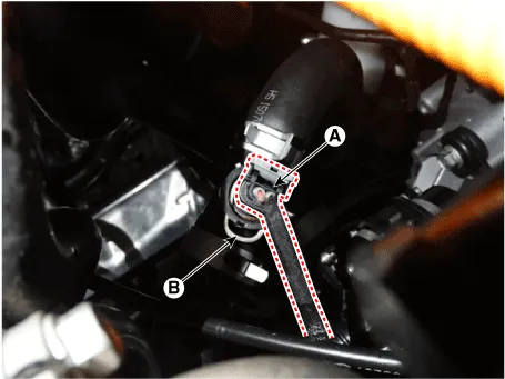
| •
| Note that engine coolant may flow out from the EGR cooler tube when removing the sensor. |
|
|
| 5. | Fill with engine coolant. (Refer to Engine Mechanical System - "Coolant") |
| •
| Install the component with the specified torques. |
| •
| Note that internal damage may occur when the component is dropped. If the component has been dropped, inspect before installing. |
|
| •
| Apply the engine coolant to the O-ring. |
|
| •
| Insert the sensor in the installation hole and be careful not to damage. |
|
| 1. | Install in the reverse order of removal. Engine coolant temperature sensor installation : 29.4 - 39.2 N.m (3.0 - 4.0 kgf.m, 21.7 - 28.9 lb-ft) |
|
Circuit Diagram[Water Temperature Control Assembly][EGR Cooler Tube]
Other information:
DescriptionThe temperature control actuator is located at the heater unit. It regulates the temperature by the procedure as follows. The signal from the control unit adjusts the position of the temperature door by operating the temperature switch. Then the temperature will be regulated by the hot/cold air ratio decided by the position of the temper
S


