Hyundai Ioniq (AE): Engine and Transaxle Assembly / Engine Mounting. Repair procedures
Hyundai Ioniq (AE) 2017-2022 Service & Repair Manual / Engine Mechanical System / Engine and Transaxle Assembly / Engine Mounting. Repair procedures
| Removal and Installation |
Roll Rod Bracket
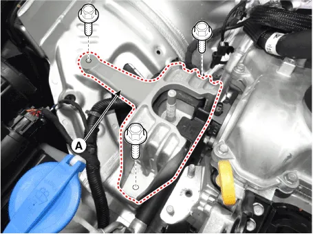
| 1. | Remove the roll rod bracket (A).
|
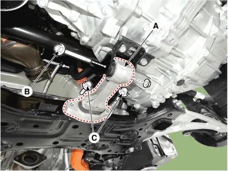
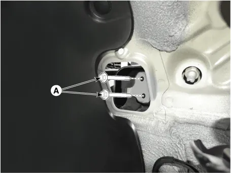
| 2. | Remove the roll rod mounting support bracket (A).
|
| 3. | Install in the reverse order of removal. |
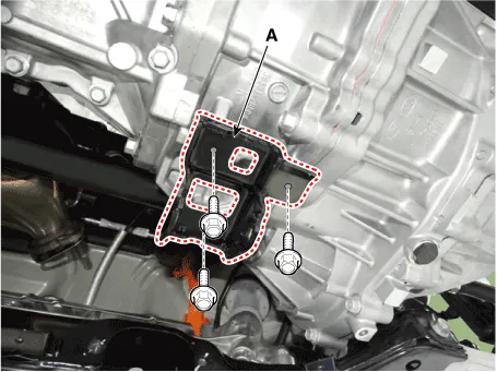
Engine Mounting Bracket
| 1. | Remove the engine room under cover. (Refer to Engine and Transaxle Assembly - "Engine Room Under Cover") |
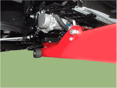
| 2. | Install the jack to the edge of oil pan to support the engine.
|

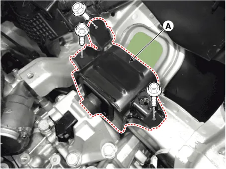
| 3. | Remove the engine mounting support bracket (A).
|
| 4. | Remove the reservoir tank. (Refer to Cooling System - "Reservoir Tank") |
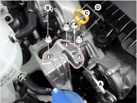
| 5. | Remove the engine mounting bracket (A).
|
| 6. | Install in the reverse order of removal. |
Transaxle Mounting Bracket
|

| 1. | Shut off the High Voltage circuit. (Refer to General Information - "High Voltage Shutoff Procedure") |
| 2. | Disconnect the battery negative terminal. |
| 3. | Remove the engine room under cover. (Refer to Engine and Transaxle Assembly - "Engine Room Under Cover") |
| 4. | Loosen the drain plug, and drain the inverter coolant. Remove the reservoir cap to help drain the coolant faster. (Refer to Hybrid Motor System - "Coolant") |
| 5. | Remove the air cleaner assembly. (Refer to Intake and Exhaust System - "Air Cleaner") |
| 6. | Remove the hybrid power control unit (HPCU). (Refer to Hybrid Control System - "Hybrid Power Control Unit (HPCU)") |
| 7. | Remove the engine control module (ECM) and DCT control module (TCM). (Refer to Engine Control / Fuel System - "Engine Control Module (ECM)") (Refer to Double Clutch Transmission (DCT) System - "DCT Control Module (TCM)") |
| 8. | Remove the hybrid power control unit (HPCU) tray. (Refer to Hybrid Control System - "Hybrid Power Control Unit (HPCU)") |
| 9. | Install the jack under the transaxle to support it. |
| 10. | Remove the service cover (A).
|

| 11. | Remove the transaxle support bracket mounting bolts (A).
|
| 12. | Remove the transaxle mounting bracket (A).
|
| 13. | Install in the reverse order of removal. |
Components1. Transaxle mounting bracket2. Roll rod bracket3. Engine mounting bracket4. Engine mounting support bracket
Removal • Be sure to read and follow the "General Safety Information and Caution" before doing any work related with the high voltage system.
Other information:
Hyundai Ioniq (AE) 2017-2022 Service & Repair Manual: Auto Defoging Actuator. Components and components location
C
Hyundai Ioniq (AE) 2017-2022 Service & Repair Manual: Front Radar Unit. Repair procedures
Removal1.Remove the front bumper.(Refer to Body - "Front Bumper")2.Disconnect the smart cruise control unit connector (A).3.Remove the smart cruise control nuit assembly (B) from thevehicle after loosening mounting bolts.Installation1.Install in the reverse order of removal.
Categories
- Manuals Home
- Hyundai Ioniq Owners Manual
- Hyundai Ioniq Service Manual
- If the 12 Volt Battery is Discharged (Hybrid Vehicle)
- Hybrid Vehicle Engine Compartment
- Engine Mechanical System
- New on site
- Most important about car

Copyright © 2026 www.hioniqae.com - 0.0224