Hyundai Ioniq (AE): Front Door / Front Door Module. Repair procedures
Hyundai Ioniq (AE) 2017-2022 Service & Repair Manual / Body (Interior and Exterior) / Front Door / Front Door Module. Repair procedures
| Replacement |
| 1. | Remove the front door window glass. (Refer to Front Door - "Front Door Window Glass") |
| 2. | Remove the front door outside handle. (Refer to Front Door - "Front Door Outside Module") |
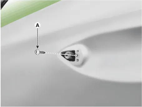
| 3. | Loosen the front door outside handle base mounting bolt (A).
|
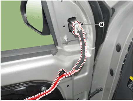
| 4. | Disconnect the front door main connector (A) and outside rear view mirror connector (B).
|
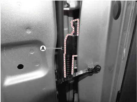
| 5. | Loosen the front door latch mounting screws.
|
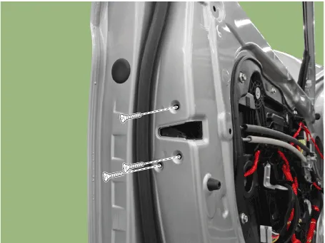
| 6. | Loosen the mounting bolts and remove the front door module (A).
|
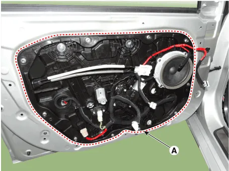
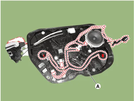
| 7. | Disconnect the connectors and front door module wiring harness (A).
|
| 8. | Remove the front door latch assembly. (Refer to Front Door - "Front Door Latch") |
| 9. | Reomove the front speaker. (Refer to Body Electrical System - "Speakers") |
| 10. | Remove the front power window motor. (Refer to Body Electrical System - "Power Window Motor") |
| 11. | Remove the side impact sensor. (Refer to Restraint - "Side Impact Sensor (SIS)") |
| 12. | To install, reverse the removal procedure.
|

Component Location 1. Front door module
Component Location 1. Front door outside handle
Other information:
Hyundai Ioniq (AE) 2017-2022 Service & Repair Manual: PTC Heater. Description and operation
DescriptionThe PTC (Positive Temperature Coefficient) heater is installed at the exit or the backside of the heater core.The PTC heater is an electric heater using a PTC element as an auxiliary heating device that supplements deficiency of interior heat source in highly effective hybrid engine.
Hyundai Ioniq (AE) 2017-2022 Service & Repair Manual: Special service tools
Special Service Tools Tool Name / Number Illustration Description LKA Compensator(09964-C1100)Used for compensating front view camera unitBCW Sensor Correction Tool Set(09958-3T500)Used to correct the blind-spot radar unit.
Categories
- Manuals Home
- Hyundai Ioniq Owners Manual
- Hyundai Ioniq Service Manual
- Checking the Coolant Level
- Suspension System
- If the 12 Volt Battery is Discharged (Hybrid Vehicle)
- New on site
- Most important about car

Copyright © 2026 www.hioniqae.com - 0.014