Hyundai Ioniq (AE): Fuel Delivery System / Fuel Pump Control Module (FPCM). Schematic diagrams
Hyundai Ioniq (AE) 2017-2022 Service & Repair Manual / Engine Control/Fuel System / Fuel Delivery System / Fuel Pump Control Module (FPCM). Schematic diagrams
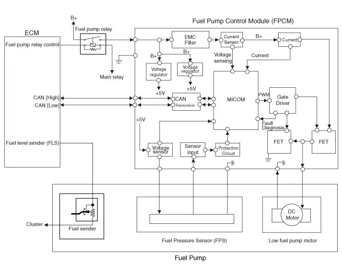
| Circuit Diagram |
| Fuel Pressure Control Module (FPCM) Terminal And Input/Output signal |

| FPCM Terminal Function |
|
Pin No
|
Discription
|
Connected to
|
| 1 | Fuel sender ground | Fuel Pump |
| 2 | Fuel pressure sensor (FPS) signal input | Fuel Pressure Sensor (FPS) |
| 3 | Fuel pressure sensor (FPS) ground (-) | Fuel Pressure Sensor (FPS) |
| 4 | Ground | Chassis Ground |
| 5 | CAN [Low] | ECM |
| 6 | Fuel sender signal | Fuel Pump |
| 7 | - | - |
| 8 | Fuel pressure sensor (FPS) Power supply (+5V) | Fuel Pressure Sensor (FPS) |
| 9 | CAN [High] | ECM |
| 10 | Battery power (B+) | Fuel Pump Relay |
DescriptionThe fuel pump control module (FPCM) is installed on the right side of the fuel tank and controls the DC motor mounted inside the low pressure fuel pump.
Removal1.Turn the ignition switch OFF and disconnect the battery negative (-) cable.2.Remove the rear seat cushion. (Refer to Body - "Rear Seat Assembly")3.
Other information:
Hyundai Ioniq (AE) 2017-2022 Service & Repair Manual: Repair procedures
Replacement1.Remove the battery (-) terminal.2.Remove the engine room under cover.(Refer to Engine Mechanical System - "Engine Room Under Cover")3.Remove the heater hose (A) and AEWP hose (B).4.Disconnect the lock pin to remove the heater hose pump connector (A).
Hyundai Ioniq (AE) 2017-2022 Service & Repair Manual: Cruise Control Switch. Components and components location
C
Categories
- Manuals Home
- Hyundai Ioniq Owners Manual
- Hyundai Ioniq Service Manual
- Checking the Coolant Level
- Theft-alarm System
- How to Connect Portable Charger (ICCB: In-Cable Control Box)
- New on site
- Most important about car

Copyright © 2026 www.hioniqae.com - 0.0132