Hyundai Ioniq (AE): Fuel Delivery System / Fuel Pump Control Module (FPCM). Repair procedures
| Removal |
| 1. | Turn the ignition switch OFF and disconnect the battery negative (-) cable. |
| 2. | Remove the rear seat cushion. (Refer to Body - "Rear Seat Assembly") |
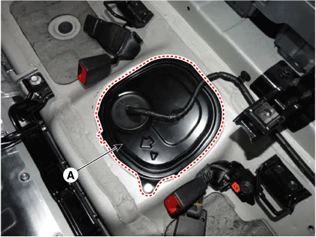
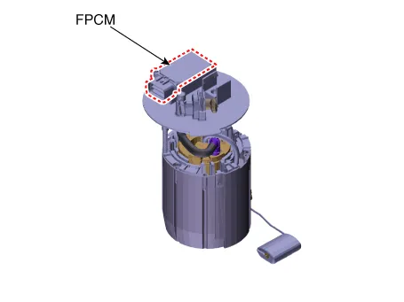
| 3. | Remove the fuel pump service cover (A).
|


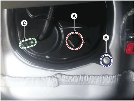
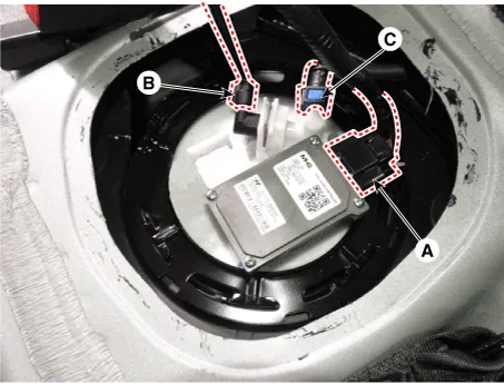
| 4. | Disconnect the fuel pump control module connector (A). |
| 5. | Disconnect the fuel pressure sensor connector (B). |
| 6. | Disconnect the fuel feed tube quick-connector (C).
|
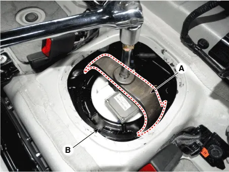
| 7. | Remove the fuel pump locking ring (B) with SST (A) [SST.: 09310-F3100].
|
| Installation |
| 1. | Install in the reverse order of removal. |
| Inspection |
| 1. | Connect the GDS to the vehicle's data link connector (DLC). |
| 2. | Check any DTCs and if exist, repair according to the DTC guide. |
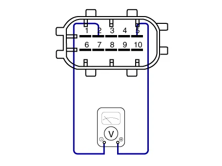
| 3. | Check the power supply voltage provided to the fuel pressure sensor (FPS).
|

| 4. | Check the voltage provided to the fuel pressure sensor (FPS) at idle.
|
| 5. | Check the fuel pressure in the low fuel line. (Refer to Fuel Delivery System - "Fuel Pressure Test")
|
Circuit DiagramFuel Pressure Control Module (FPCM) Terminal And Input/Output signalFPCM Terminal Function Pin No Discription Connected to 1Fuel sender groundFuel Pump2Fuel pressure sensor (FPS) signal inputFuel Pressure Sensor (FPS)3Fuel pressure sensor (FPS) ground (-)Fuel Pressure Sensor (FPS)4GroundChassis Ground5CAN [Low]ECM6Fuel sender signalFuel Pump7--8Fuel pressure sensor (FPS) Power supply (+5V)Fuel Pressure Sensor (FPS)9CAN [High]ECM10Battery power (B+)Fuel Pump Relay
DescriptionThe fuel pressure sensor (FPS) is installed on the top of the low pressure fuel pump and measures the pressure in the low pressure fuel line.
Other information:
Hyundai Ioniq (AE) 2017-2022 Service & Repair Manual: High voltage shut-off procedures
High Voltage Shut-off Procedures • Be sure to read and follow the "General Safety Information and Caution" before doing any work related with the high voltage system. Failure to follow the safety instructions may result in serious electrical injuries.
Hyundai Ioniq (AE) 2017-2022 Service & Repair Manual: Rear Corner Radar Unit. Repair procedures
Removal1.Disconnect the negative (-) battery terminal.2.Remove the rear bumper.(Refer to Body - "Rear Bumper")3.Remove the rear corner radar unit (A) after loosening the mounting nuts. • Take care not to separate the bracket from rear bumper when removing the rear corner radar sensor.
Categories
- Manuals Home
- Hyundai Ioniq Owners Manual
- Hyundai Ioniq Service Manual
- Maintenance
- Brake System
- Suspension System
- New on site
- Most important about car
