Hyundai Ioniq (AE): Fuel Delivery System / Fuel Pump. Repair procedures
Hyundai Ioniq (AE) 2017-2022 Service & Repair Manual / Engine Control/Fuel System / Fuel Delivery System / Fuel Pump. Repair procedures
| Inspection |
[Fuel Sender]
| 1. | Using an ohmmeter, measure the resistance between terminals 1 and 6 of sender connector (A) at each float level.
|

| 2. | Also check that the resistance changes smoothly when the float is moved from "E" to "F".
|
| Removal |
| 1. | Turn the ignition switch OFF and disconnect the battery negative (-) cable. |
| 2. | Remove the rear seat cushion. (Refer to Body - "Rear Seat Assembly") |
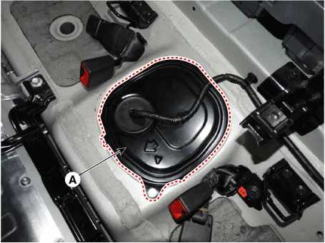
| 3. | Remove the fuel pump service cover (A).
|


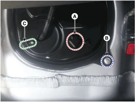
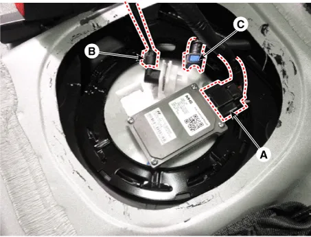
| 4. | Disconnect the fuel pump control module connector (A). |
| 5. | Disconnect the fuel pressure sensor connector (B). |
| 6. | Disconnect the fuel feed tube quick-connector (C).
|
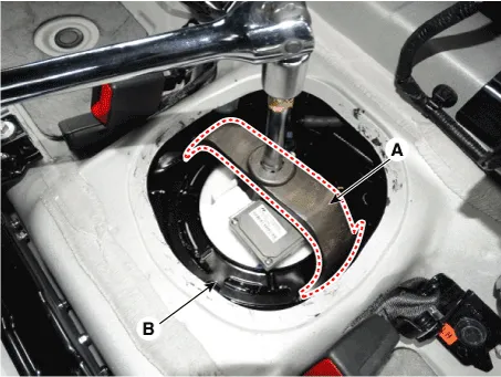
| 7. | Remove the fuel pump locking ring (B) with SST (A) [SST.: 09310-F8100].
|
| 8. | Remove the fuel pump (A).
|

| Installation |
| 1. | Install in the reverse order of removal. |
Removal1.Turn the ignition switch OFF and disconnect the battery negative (-) cable.2.Remove the rear seat cushion. (Refer to Body - "Rear Seat Assembly")3.
Removal1.Remove the fuel pump.(Refer to Fuel Delivery System - "Fuel Pump") 2.Disconnect the fuel pump motor connector (A) and fuel sender connector (B).
Categories
- Manuals Home
- Hyundai Ioniq Owners Manual
- Hyundai Ioniq Service Manual
- Checking the Coolant Level
- Transmission Gear Oil. Repair procedures
- Jump starting procedure
- New on site
- Most important about car

Copyright © 2026 www.hioniqae.com - 0.0123