Hyundai Ioniq (AE): Fuel Delivery System / Fuel Filter. Repair procedures
| Removal |
| 1. | Remove the fuel pump. (Refer to Fuel Delivery System - "Fuel Pump") |
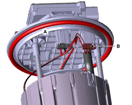
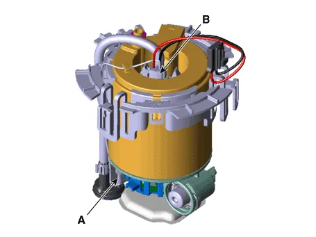
| 2. | Disconnect the fuel pump motor connector (A) and fuel sender connector (B).
|
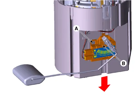
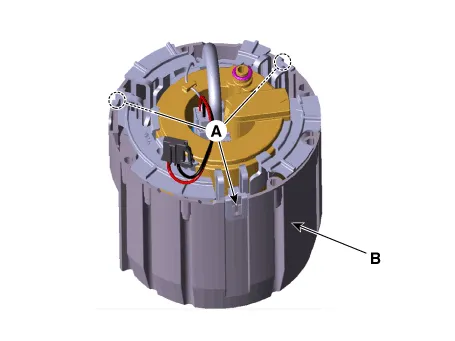
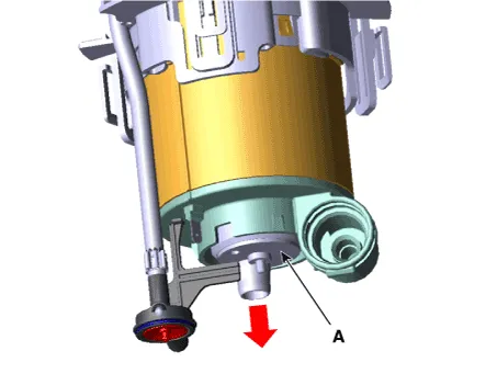
| 3. | Press the fixing hook (A) with a driver and then remove fuel sender (B) in the arrow direction.
|
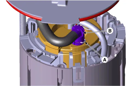
| 4. | Disconnect the fuel feed tube (B) after removing the fixing pin (A).
|
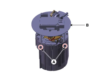
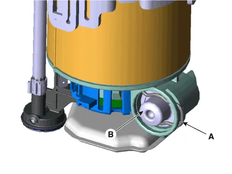
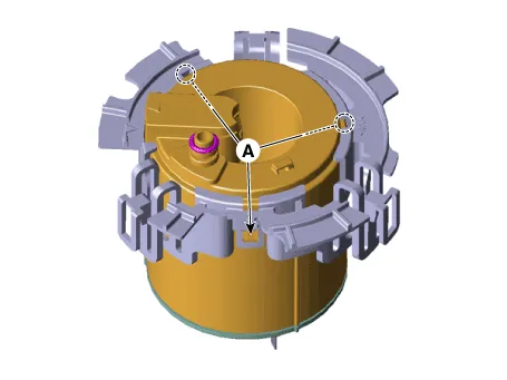
| 5. | Remove the head assembly (B) after releasing the fixing hooks (A).
|
| 6. | Remove the reservoir-cup (B) after releasing the fixing hooks (A).
|
| 7. | Disconnect the ground line (A). |
| 8. | Disconnect the fuel pump motor connector (A).
|
| 9. | Disconnect the fuel pressure regulator (B) after removing the fixing pin (A).
|
| 10. | Remove the free filter p (B) after releasing the fixing hooks (A).
|
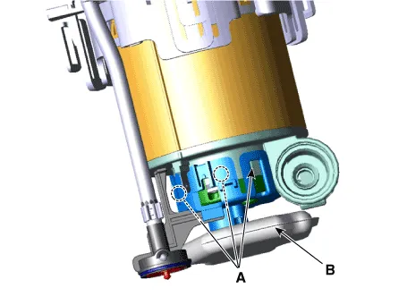
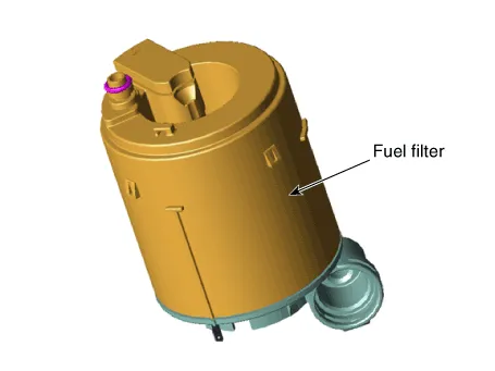
| 11. | Remove the fuel pump motor (A) from the fuel filter.
|
| 12. | Remove the fuel filter from the bracket after releasing the fixing hooks (A).
|
| Installtion |
| 1. | Install in the reverse order of removal. |
Inspection[Fuel Sender] 1.Using an ohmmeter, measure the resistance between terminals 1 and 6 of sender connector (A) at each float level. Pin No Discription 1Fuel sender ground 2Fuel pressure sensor (FPS) signal input 3Fuel pressure sensor (FPS) ground (-) 4Ground 5CAN [Low] 6Fuel sender signal 7- 8Fuel pressure sensor (FPS) Power supply (+5V) 9CAN [High] 10Battery power (B+) 2.
Removal1.Remove the fuel pump.(Refer to Fuel Delivery System - "Fuel Pump") 2.Disconnect the fuel pump motor connector (A) and fuel sender connector (B).
Other information:
Hyundai Ioniq (AE) 2017-2022 Service & Repair Manual: Description and operation
DescriptionIn ordinary cars, the mechanical water pump mounted on the engine for heating purposes is activated to circulate the cooling water, but in hybrid cars, AEWP is used to circulate the cooling water when the engine is not operating. Classification System Cooling water used
Hyundai Ioniq (AE) 2017-2022 Service & Repair Manual: Schematic diagrams
Trouble Symptom ChartsComponent Parts and Function Outline Component part Function Cruise Control Switch Input the set speed and distance to the SCC ECU. Instrument Cluster Display various information inputted from SCC.
Categories
- Manuals Home
- Hyundai Ioniq Owners Manual
- Hyundai Ioniq Service Manual
- Brake System
- General Information
- Suspension System
- New on site
- Most important about car
