Hyundai Ioniq (AE): Fuel Delivery System / Fuel Pump Motor. Repair procedures
Hyundai Ioniq (AE) 2017-2022 Service & Repair Manual / Engine Control/Fuel System / Fuel Delivery System / Fuel Pump Motor. Repair procedures
| Removal |
| 1. | Remove the fuel pump. (Refer to Fuel Delivery System - "Fuel Pump") |
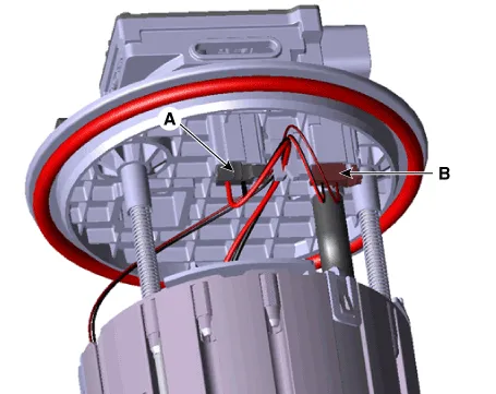
| 2. | Disconnect the fuel pump motor connector (A) and fuel sender connector (B).
|
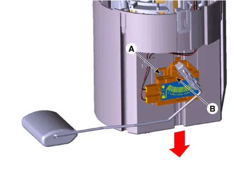
| 3. | Press the fixing hook (A) with a driver and then remove fuel sender (B) in the arrow direction.
|
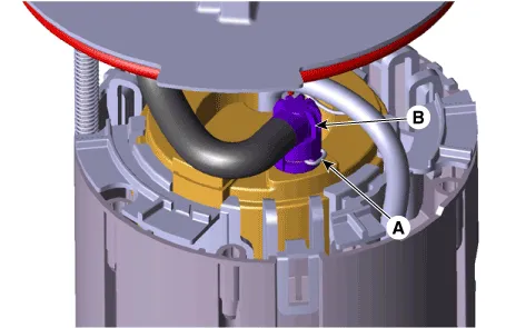
| 4. | Disconnect the fuel feed tube (B) after removing the fixing pin (A).
|
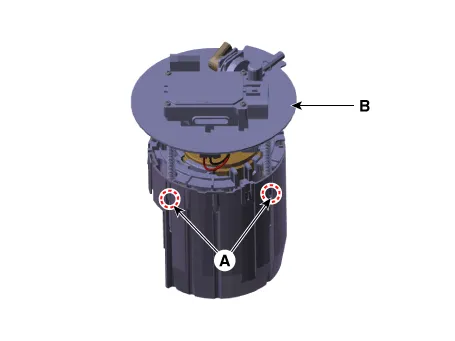
| 5. | Remove the head assembly (B) after releasing the fixing hooks (A).
|
| 6. | Remove the reservoir-cup (B) after releasing the fixing hooks (A).
|
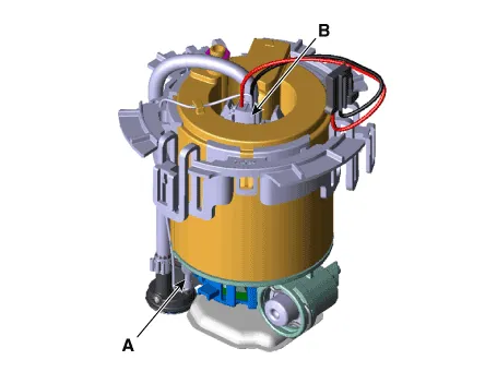
| 7. | Disconnect the ground line (A). |
| 8. | Disconnect the fuel pump motor connector (A).
|
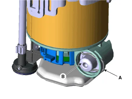
| 9. | Disconnect the fuel pressure regulator (B) after removing the fixing pin (A).
|
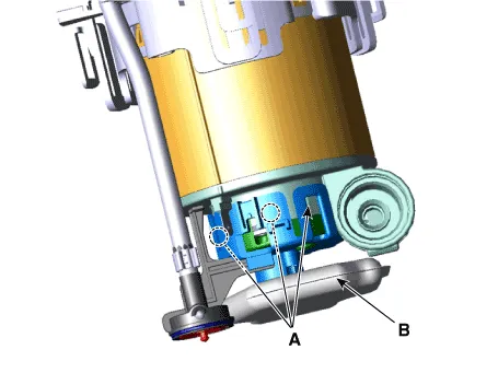
| 10. | Remove the free filter p (B) after releasing the fixing hooks (A).
|
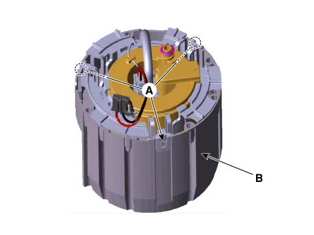
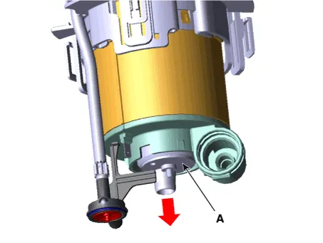
| 11. | Remove the fuel pump motor (A) from the fuel filter.
|

| Installtion |
| 1. | Install in the reverse order of removal. |
Removal1.Remove the fuel pump.(Refer to Fuel Delivery System - "Fuel Pump") 2.Disconnect the fuel pump motor connector (A) and fuel sender connector (B).
Removal1.Remove the fuel pump.(Refer to Fuel Delivery System - "Fuel Pump") 2.Disconnect the fuel pump motor connector (A) and fuel sender connector (B).
Other information:
Hyundai Ioniq (AE) 2017-2022 Service & Repair Manual: Smart Cruise Control (SCC) Switch. Repair procedures
Removal1.Disconnect the negative (-) battery terminal.2.Remove the steering wheel assembly.(Refer to Steering System -"Steering Wheel")3.Remove the steering back cover (A).4.Remove the steering remote control connector (A).5.Remove the steering remote control (A), after loosening the screws.
Hyundai Ioniq (AE) 2017-2022 Service & Repair Manual: Cruise Control Switch. Components and components location
C
Categories
- Manuals Home
- Hyundai Ioniq Owners Manual
- Hyundai Ioniq Service Manual
- Engine Control/Fuel System
- If the 12 Volt Battery is Discharged (Hybrid Vehicle)
- Body (Interior and Exterior)
- New on site
- Most important about car

Copyright © 2026 www.hioniqae.com - 0.0217