
Hyundai Ioniq (AE): Fuel Delivery System / Fuel Sender. Repair procedures
| Removal |
| 1. | Remove the fuel pump. (Refer to Fuel Delivery System - "Fuel Pump") |
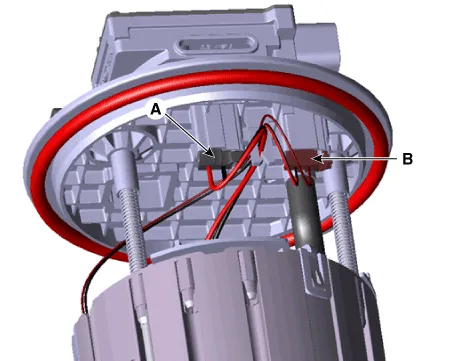
| 2. | Disconnect the fuel pump motor connector (A) and fuel sender connector (B).
|
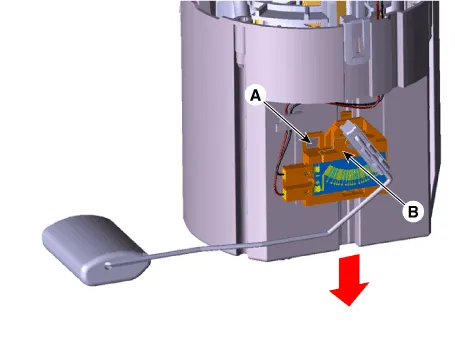
| 3. | Press the fixing hook (A) with a driver and then remove fuel sender (B) in the arrow direction.
|
| Installation |
| 1. | Install in the reverse order of removal. |
Removal1.Remove the fuel pump.(Refer to Fuel Delivery System - "Fuel Pump") 2.Disconnect the fuel pump motor connector (A) and fuel sender connector (B).
Removal1.Remove the fuel pump.(Refer to Fuel Delivery System - "Fuel Pump") 2.Disconnect the fuel pump motor connector (A) and fuel sender connector (B).
Other information:
Hyundai Ioniq (AE) 2017-2022 Service & Repair Manual: Heater Unit. Components and components location
Component Location1. Heater unit assemblyCompoents1. Heater core cover2. Heater core & Seal assembly3. Mode actuator [LH]4. Temperature control actuator [LH]5. Shower duct [LH]6. Duct sensor [Floor]7. PTC Heater8. Duct sensor [Vent]9. Heater & Evaporator lower case10.
Hyundai Ioniq (AE) 2017-2022 Service & Repair Manual: Mode Control Actuator. Repair procedures
Inspection1.Turn the ignition switch OFF.2.Disconnect the mode control actuator connector.3.Verify that the mode control actuator operates to the defrost mode when connecting 12V to terminal 3 and grounding terminal 4.Verify that the mode control actuator operates to the vent mode when connected in reverse.
Categories
- Manuals Home
- Hyundai Ioniq Owners Manual
- Hyundai Ioniq Service Manual
- If the 12 Volt Battery is Discharged (Hybrid Vehicle)
- Engine Mechanical System
- Front Disc Brake. Repair procedures
- New on site
- Most important about car
