Hyundai Ioniq (AE): Lighting System / Head Lamps. Repair procedures
Hyundai Ioniq (AE) 2017-2022 Service & Repair Manual / Body Electrical System / Lighting System / Head Lamps. Repair procedures
| Head Lamp Aiming Instructions |
[Mechanical Aiming]
The head lamps should be aimed with the proper beam-setting equipment, and in accordance with the equipment manufacturer's instructions.
|

Alternately turn the adjusting gear to adjust the head lamp aiming. If beam-setting equipment is not available, proceed as follows :
| 1. | Inflate the tires to the specified pressure and remove any loads from the vehicle except the driver, spare tire, and tools. |
| 2. | The vehicle should be placed on a flat floor. |
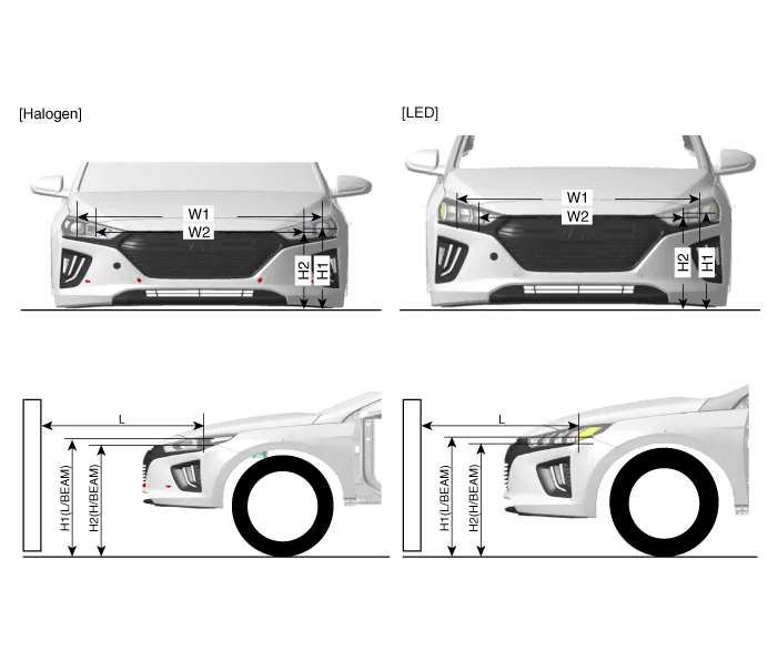
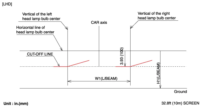
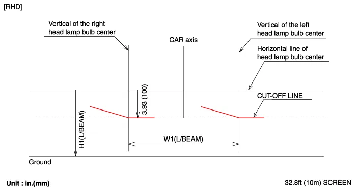
| 3. | . Draw vertical lines (Vertical lines passing through respective head lamp centers) and a horizontal line (Horizontal line passing through center of head lamps) on the screen. |
| 4. | With the head lamp and battery in normal condition, aim the head lamps so the brightest portion falls on the horizontal and vertical lines. A : Vertical (High beam / Low beam) B : Horizontal (Low beam) [Halogen]
[LED]
|
Head Lamp and Fog Lamp Aiming Point
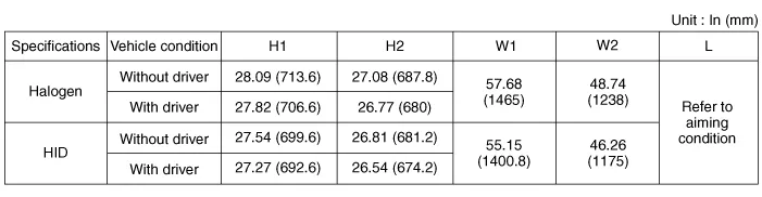
| 1. | Head Lamp (Low beam)
|
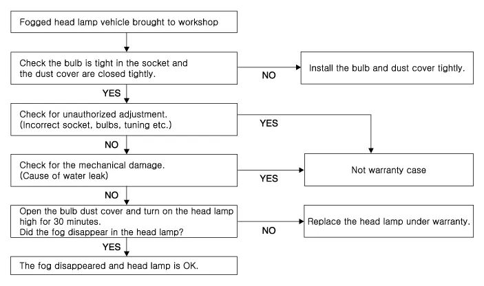
Head Lamp Fogging
Check the below instruction procedure when the head lamp is fogged.
| Removal |
| 1. | Disconnect the negative (-) battery terminal. |
| 2. | Remove the front bumper cover. (Refer to Body - "Front Bumper Cover") |
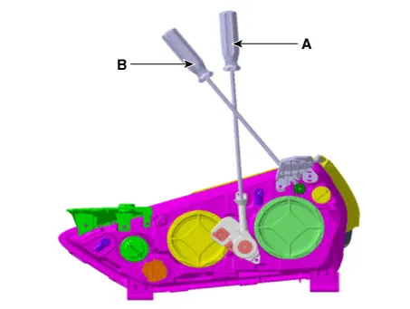
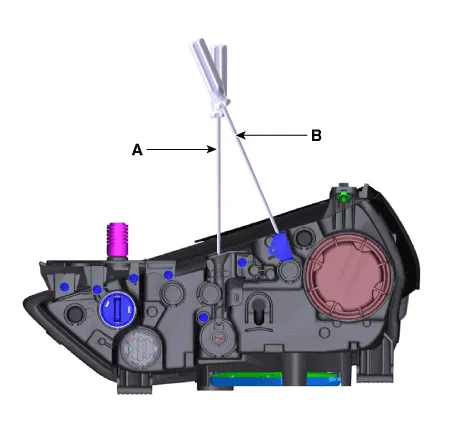
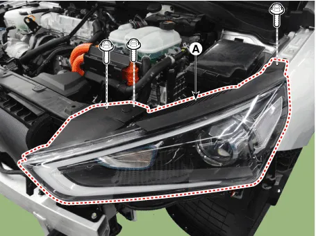
| 3. | Disconnect the head lamp connector (A).
|
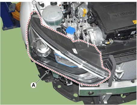
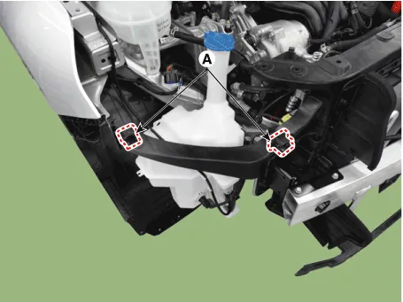
| 4. | Remove the head lamp (B) mounting bolts.
|
| Installation |
| 1. | Install the head lamp assembly after connecting the connector. |
| 2. | Install the front bumper corver. |
| 3. | Connect the negative (-) battery terminal. |
| Replacement |
[Turn Signal Lamp]
| 1. | Turn the head lamp power off. |
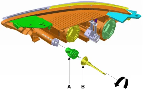
| 2. | Remove the bulb socket (B) and turn signal lamp bulb (A) from the lamp assembly.
|
[HID]
| 1. | Remove the head lamp. |
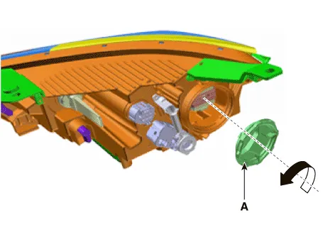
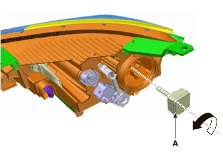
| 2. | Remove the bulb caps from the head lamp assembly after turning in the counter clock-wise direction.
|
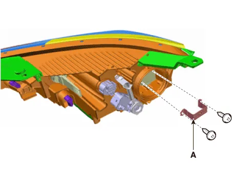
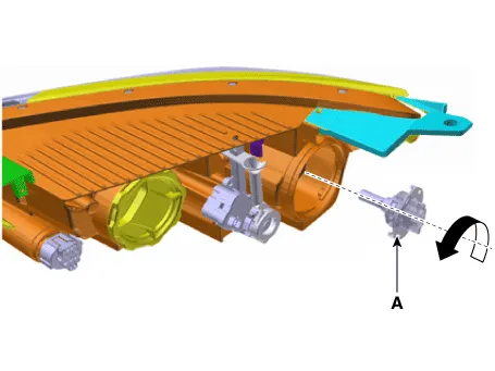
| 3. | Remove the braket (A) after loosening the mounting screws.
|
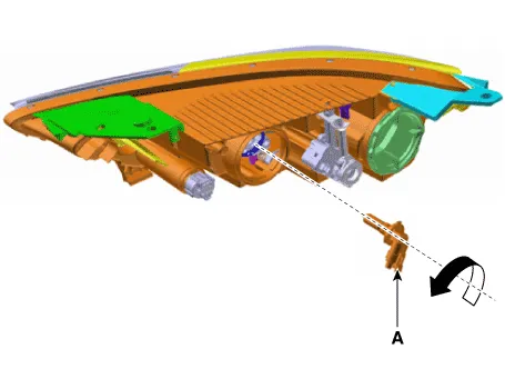
| 4. | Remove the ignitor (A) after disconnecting the ignitor connector.
|
| 5. | To install, reverse the removal procedure.
|

[Bulb (High / Low Beam)]
| 1. | Remove the head lamp. |
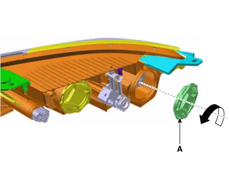
| 2. | Remove the bulb cap (A) from the head lamp assembly after turning in the counter clock-wise direction. [Low beam]
[High beam]
|
| 3. | Disconnect the low beam connector. |
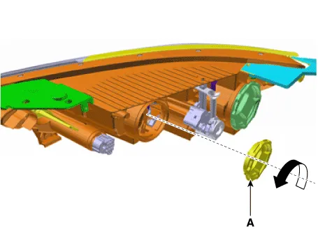
| 4. | Remove the low bulb (A) from the head lamp assembly after turning in the counter clock-wise direction.
|
| 5. | Disconnect the high lamp connector. |
| 6. | Remove the high bulb (A) from the head lamp assembly after turning in the counter clock-wise direction.
|
| 7. | To install, reverse the removal procedure. |
[Ballast]
| 1. | Remove the head lamp. |
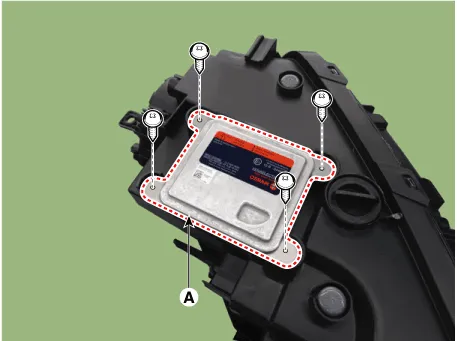
| 2. | Remove the ballast (A) after loosening the mounting screws.
|
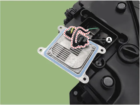
| 3. | Disconnect the ballast connector (A).
|
| 4. | To install, reverse the removal procedure.
|
Components[Standard]1. Head lamp (Low)2. Head lamp (High)3. Turn signal lamp4. Dust cap5. Position lamp
Removal[Room Lamp]1.Disconnect the negative (-) battery terminal.2.Using a screwdriver or remover, Separate the room lamp lens (A) from the room lamp. • Put on gloves to prevent hand injuries.
Other information:
Hyundai Ioniq (AE) 2017-2022 Service & Repair Manual: A/C Pressure Transducer. Repair procedures
Inspection • Before measuring the pressure of the refriferant line, check whether the refrigerant amount is charged in accordance with the specified charging amount.(Refer to Heating, Ventilation, Air Conditioning - "Specifications")1.
Hyundai Ioniq (AE) 2017-2022 Service & Repair Manual: Cruise Control Switch. Components and components location
C
Categories
- Manuals Home
- Hyundai Ioniq Owners Manual
- Hyundai Ioniq Service Manual
- Hybrid Vehicle Engine Compartment
- Maintenance
- Checking the Coolant Level
- New on site
- Most important about car

Copyright © 2026 www.hioniqae.com - 0.0188