Hyundai Ioniq (AE): Lighting System / Room Lamp. Repair procedures
Hyundai Ioniq (AE) 2017-2022 Service & Repair Manual / Body Electrical System / Lighting System / Room Lamp. Repair procedures
| Removal |
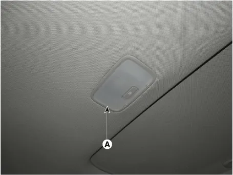
[Room Lamp]
| 1. | Disconnect the negative (-) battery terminal. |
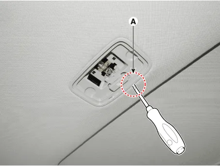
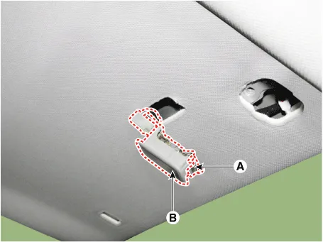
| 2. | Using a screwdriver or remover, Separate the room lamp lens (A) from the room lamp.
|

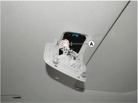
| 3. | If it is necessary to replace the bulb, remove the bulb (A) after disengaging the room lamp lens. |
| 4. | Disengage the room lamp (B) after loosening the mounting screws.
|
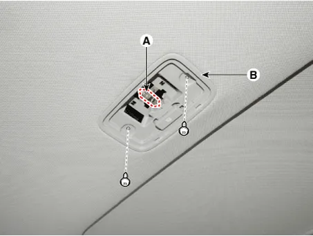

| 5. | Remove the room lamp assembly after disconnect the room lamp connector.
|
[Vanity Lamp]
| 1. | Separate the vanity Lamp (A) from the roof trim after disengaging the mounting clip (B).
|
| Installation |
[Room Lamp]
| 1. | Install the room lamp after connect the connector. |
| 2. | Install the room lamp lens |
| 3. | Connect the negative (-) battery terminal. |
[Vanity Lamp]
| 1. | Install the vanity lamp. |
| 2. | Connect the negative (-) battery terminal. |
Head Lamp Aiming Instructions[Mechanical Aiming]The head lamps should be aimed with the proper beam-setting equipment, and in accordance with the equipment manufacturer's instructions.
Inspection1.Remove the overhead console lamp assembly then check for continuity between terminals. If the continuity is not as specified, replace the map lamp switch.
Other information:
Hyundai Ioniq (AE) 2017-2022 Service & Repair Manual: PTC Heater. Repair procedures
InspectionOperating Logic Test (Manual only)Inspect the PTC operation by confirmation logic as follows.1.Entering(1)Set the Floor mode and maximum heating position.(2)Turn off the blower switch.(3)Press the intake (recirculation) button 5 times or more.
Hyundai Ioniq (AE) 2017-2022 Service & Repair Manual: Auto Defoging Actuator. Components and components location
C
Categories
- Manuals Home
- Hyundai Ioniq Owners Manual
- Hyundai Ioniq Service Manual
- Theft-alarm System
- DCT(Dual Clutch Transmission) System
- Maintenance
- New on site
- Most important about car

Copyright © 2026 www.hioniqae.com - 0.0253