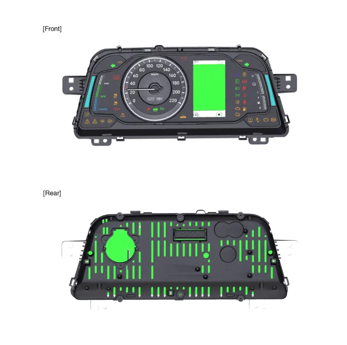
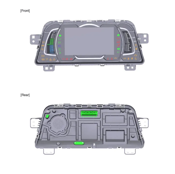
Hyundai Ioniq (AE): Indicators And Gauges / Instrument Cluster. Components and components location
| Components |
|
No
|
Description
|
No
|
Description
|
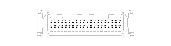
| 1 | Ground | 21 | Trip switch (-) |
| 2 | Illumination (-) | 22 | Trip switch 1 (+) |
| 3 | Rheostat switch (Down) | 23 | Trip switch 2 (+) |
| 4 | Rheostat switch (Up) | 24 | AT ('P' Position) |
| 5 | - | 25 | AT ('R' Position) |
| 6 | Oil press switch input | 26 | AT ('N' Position) |
| 7 | Washer level (Low) | 27 | AT ('D' Position) |
| 8 | - | 28 | AT ('S' Position) |
| 9 | - | 29 | Multimedia - CAN (Low) |
| 10 | Drive mode switch input | 30 | Multimedia - CAN (High) |
| 11 | Detent output | 31 | - |
| 12 | - | 32 | Chassis - CAN (High) |
| 13 | - | 33 | Chassis - CAN (Low) |
| 14 | Fuel sender (+)_Input | 34 | - |
| 15 | - | 35 | - |
| 16 | Fuel sender (-)_Input | 36 | - |
| 17 | Immobillizer input | 37 | Ground |
| 18 | Vehicle speed output | 38 | IGN 3 |
| 19 | Airbag input (+) | 39 | IGN 1 |
| 20 | Tail lamp | 40 | Battery (+) |
Troubleshooting Error Item Failure symptom Inspection items Detailed inspections Relevant Parts/ Components Screen displayTFT-LCD screen does not turn on1)Connector attachments2)Components1)Check the connector attachments2)Check B+, IGN and GND wiring3)Check the components Connectors, wiring, fuses, dashboardWarning lightAirbag warning lamp malfunction1)Connector attachments2)C-CAN3)Components1)Check airbag + signal (connectors)2)Check C-CAN (ACU4) signal3)Check the FPC attachment inside the dashboardACU Connectors, wiring, fuses, dashboardMode conversionIntegrated driving mode malfunction1)Connector attachments2)Switch3)Components1)Check the switch input (connector)2)Check the switch signal input(disconnection or shorting)3)Check conversion with dashboard componentSwitch connector, wiring dashboardIlluminationInterior light brightness cannot be controlled.
DescriptionCommunication Network Diagram Abbreviation Expalnation AAFActive Air FlapACUAirbag Control UnitAEBAutonomous Emergency BrakingAHBActive Hybrid Brake SystemAMPAmplifierAVNHead Unit (Audio / AVN)B_CANBody Controller Area NetworkBCMBody Control ModuleBMSBattery Management SystemBSDBlind Spot DetectionC_CANChassis Controller Area NetworkCARMERARear View CarmeraCLUCluster ModuleDATCDual Automatic Temp ControlFPCMFuel Pump Control ModuleHPCUHybrid Power UnitIGPMIntergrated Gateway & Power control ModuleLDWSLane Departure Warning SystemM_CANMulti media Controller Area NetworkMDPS Motor Driven Power SteeringP_CANPowertrain Controller Area NetworkPASParking Assist SystemSJBSmart Junction BlockSMKSmart Key UnitTCM(DCT)Double Clutch Transmission UnitVESSVirtual Engine Sound SystemCluster Variant CodingAs we have more options (ESC, MDPS, SCC, etc.
Other information:
Hyundai Ioniq (AE) 2017-2022 Service & Repair Manual: General safety information and caution
Safety PrecautionPrecautions To Take Before Servicing High Voltage System • Since hybrid vehicles contain a high voltage battery, if the high voltage system or vehicles are handled incorrectly, this might lead to a serious accidents like electric shock and electric leakage.
Hyundai Ioniq (AE) 2017-2022 Service & Repair Manual: Front Radar Unit. Repair procedures
Removal1.Remove the front bumper.(Refer to Body - "Front Bumper")2.Disconnect the smart cruise control unit connector (A).3.Remove the smart cruise control nuit assembly (B) from thevehicle after loosening mounting bolts.Installation1.Install in the reverse order of removal.
Categories
- Manuals Home
- Hyundai Ioniq Owners Manual
- Hyundai Ioniq Service Manual
- Brake System
- Heating, Ventilation and Air Conditioning
- Hybrid Vehicle Engine Compartment
- New on site
- Most important about car
