Hyundai Ioniq (AE): Indicators And Gauges / Instrument Cluster. Description and operation
| Description |

| Abbreviation | Expalnation |
| AAF | Active Air Flap |
| ACU | Airbag Control Unit |
| AEB | Autonomous Emergency Braking |
| AHB | Active Hybrid Brake System |
| AMP | Amplifier |
| AVN | Head Unit (Audio / AVN) |
| B_CAN | Body Controller Area Network |
| BCM | Body Control Module |
| BMS | Battery Management System |
| BSD | Blind Spot Detection |
| C_CAN | Chassis Controller Area Network |
| CARMERA | Rear View Carmera |
| CLU | Cluster Module |
| DATC | Dual Automatic Temp Control |
| FPCM | Fuel Pump Control Module |
| HPCU | Hybrid Power Unit |
| IGPM | Intergrated Gateway & Power control Module |
| LDWS | Lane Departure Warning System |
| M_CAN | Multi media Controller Area Network |
| MDPS | Motor Driven Power Steering |
| P_CAN | Powertrain Controller Area Network |
| PAS | Parking Assist System |
| SJB | Smart Junction Block |
| SMK | Smart Key Unit |
| TCM(DCT) | Double Clutch Transmission Unit |
| VESS | Virtual Engine Sound System |
| 1. | High speed CAN communication (C-CAN)
|
| 2. | Low speed CAN communication (MM-CAN)
|
| 3. | Sound output Instrument cluster and the external speakers connected to the output of the various beeps and sound effects. If External AMP is applied, the directional alarm is outputted through the amp.
|

| 4. | User Setting Mode (USM) Setting can be changed by using switchs (Menu, UP, Down and OK button). There are many items (for example, In/Out Seat Synchronization, In/Out Steering Wheel Synchronization, Auto Door Lock, Auto Door Lock Deactivate, Head Lamp Escort, Welcome Light, Welcome Sound, One Touch Turn Signal, Average Fuel Consumption Auto Reset, Brightness, and Content Setup) that can be set and customized. The signal flow during setting is as follows.
|

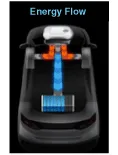
| 1. | ECO and power guage
|
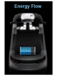
| 2. | SOC(State of Charge) guage
|

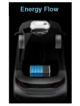
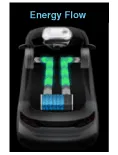
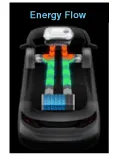
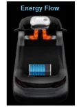
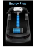
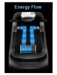
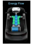
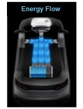
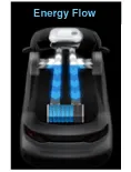
| 3. | Energy Flow
|
Components[Super Vision Type(4.3" Color TFT)][Super Vision Type(7" TFT)]Connector Pin Information No Description No Description 1Ground21Trip switch (-)2Illumination (-)22Trip switch 1 (+)3Rheostat switch (Down)23Trip switch 2 (+)4Rheostat switch (Up)24AT ('P' Position)5-25AT ('R' Position)6Oil press switch input26AT ('N' Position)7Washer level (Low)27AT ('D' Position)8-28AT ('S' Position)9-29Multimedia - CAN (Low)10Drive mode switch input30Multimedia - CAN (High)11Detent output31-12-32Chassis - CAN (High)13-33Chassis - CAN (Low)14Fuel sender (+)_Input34-15-35-16Fuel sender (-)_Input36-17Immobillizer input37Ground18Vehicle speed output38IGN 319Airbag input (+)39IGN 120Tail lamp40Battery (+)
Circuit Diagram[Super Vision Type(4.3" Color TFT)][Super Vision Type(7" TFT)]
Other information:
Hyundai Ioniq (AE) 2017-2022 Service & Repair Manual: Intake Actuator. Components and components location
C
Hyundai Ioniq (AE) 2017-2022 Service & Repair Manual: Parking Distance Warning (PDW) Sensor. Repair procedures
Removal1.Disconnect the negative (-) battery terminal.2.Remove the front / rear bumper cover.(Refer to Body - "Front Bumper Cover")(Refer to Body - "Rear Bumper Cover")3.Disconnect the connector (A) from the parking assist sensor.4.Remove the sensor (A) by pulling out both ends of the sensor holder.
Categories
- Manuals Home
- Hyundai Ioniq Owners Manual
- Hyundai Ioniq Service Manual
- Engine Mechanical System
- Engine Clutch System
- Suspension System
- New on site
- Most important about car
