Hyundai Ioniq (AE): Indicators And Gauges / Instrument Cluster. Schematic diagrams
| Circuit Diagram |
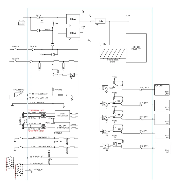

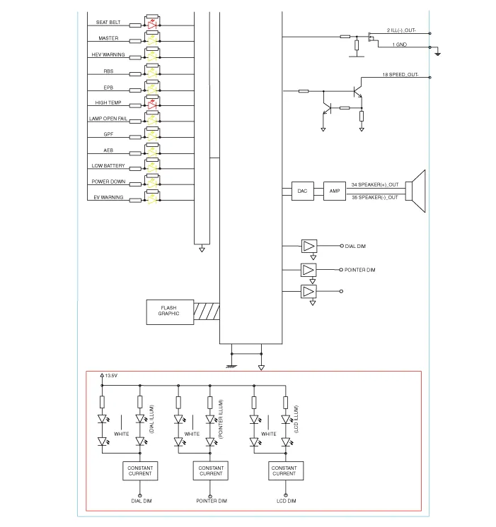
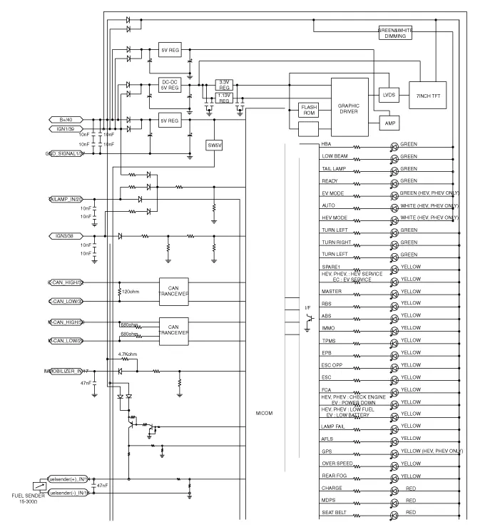
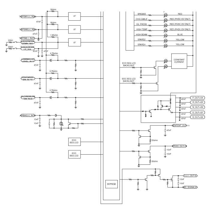
DescriptionCommunication Network Diagram Abbreviation Expalnation AAFActive Air FlapACUAirbag Control UnitAEBAutonomous Emergency BrakingAHBActive Hybrid Brake SystemAMPAmplifierAVNHead Unit (Audio / AVN)B_CANBody Controller Area NetworkBCMBody Control ModuleBMSBattery Management SystemBSDBlind Spot DetectionC_CANChassis Controller Area NetworkCARMERARear View CarmeraCLUCluster ModuleDATCDual Automatic Temp ControlFPCMFuel Pump Control ModuleHPCUHybrid Power UnitIGPMIntergrated Gateway & Power control ModuleLDWSLane Departure Warning SystemM_CANMulti media Controller Area NetworkMDPS Motor Driven Power SteeringP_CANPowertrain Controller Area NetworkPASParking Assist SystemSJBSmart Junction BlockSMKSmart Key UnitTCM(DCT)Double Clutch Transmission UnitVESSVirtual Engine Sound SystemCluster Variant CodingAs we have more options (ESC, MDPS, SCC, etc.
Removal • Put on gloves to protect your hands.• When prying with a flat-tip screwdriver, wrap it with protective tape, and apply protective tape around the related parts, to prevent damage.
Other information:
Hyundai Ioniq (AE) 2017-2022 Service & Repair Manual: Auto Defoging Actuator. Description and operation
DescriptionThe auto defogging sensor is installed on front window glass. The sensor judges and sends signal if moisture occurs to blow out wind for defogging. The air conditioner control module receives a signal from the sensor and restrains moisture and eliminates defog by the intake actuator, A/C, auto defogging actuator, blower motor rpm and mod
Hyundai Ioniq (AE) 2017-2022 Service & Repair Manual: Blower Motor. Repair procedures
Inspection1.Connect the battery voltage and check the blower motor rotation.2.If the blower motor does not operate well, substitute with a known-good blower motor and check for proper operation.3.Replace the blower motor if it is proved that there is a problem with it.
Categories
- Manuals Home
- Hyundai Ioniq Owners Manual
- Hyundai Ioniq Service Manual
- Hybrid Control System
- Theft-alarm System
- Troubleshooting
- New on site
- Most important about car
